Showing posts with label QinQ. Show all posts
Fun with QinQ tunnels - Part 4: Never trunk a tunnel VLAN

Fun with QinQ tunnels - Part 4: Never trunk a tunnel VLAN

We are back to playing with QinQ tunnels. This time solving a Layer 2 loop issue.

If you recall from part 1 we have had to do a bit of a McGyver and loop a cable in and out of our switch to bring up the tunnel. It worked well in that post, but now it's time to open up the tunnel a bit more and allow more vlans through it.

Our QinQ trunk port is configured as follows:
3750#sh run int fa1/0/1
Building configuration...

Current configuration : 263 bytes
!
interface FastEthernet1/0/1
 description **** QinQ vlan ****
 switchport access vlan 500
 switchport trunk encapsulation dot1q
 switchport mode dot1q-tunnel
 ip access-group 101 in
 no keepalive
 l2protocol-tunnel cdp
 l2protocol-tunnel stp
 no cdp enable
end
And our access port is configure as:
3750#sh run int fa1/0/17
Building configuration...

Current configuration : 177 bytes
!
interface FastEthernet1/0/17
 description **** Cust trunk ****
 switchport trunk encapsulation dot1q
 switchport trunk allowed vlan 4,10,11,61,62,63
 switchport mode trunk
end
So the logical solution to allow all our vlans to communicate over the QinQ would be to change the allowed VLAN list to "all", this should do it, right?

Not so much, and behold the problem when we do this:
3750(config-if)#int fa1/0/17
3750(config-if)#switchport trunk allowed vlan all
3750(config-if)#exit
3750(config)#exit
03:34:26: %PM-4-ERR_DISABLE: l2ptguard error detected on Fa1/0/1, putting Fa1/0/1 in err-disable state
3750#
03:34:27: %LINEPROTO-5-UPDOWN: Line protocol on Interface FastEthernet1/0/1, changed state to down
03:34:27: %LINEPROTO-5-UPDOWN: Line protocol on Interface FastEthernet1/0/17, changed state to down
03:34:27: %SYS-5-CONFIG_I: Configured from console by console
03:34:28: %LINK-3-UPDOWN: Interface FastEthernet1/0/1, changed state to down
03:34:28: %LINK-3-UPDOWN: Interface FastEthernet1/0/17, changed state to down
3750#
Immediately we find that our switch detects a layer 2 loop and is error disabled: "%PM-4-ERR_DISABLE: l2ptguard error detected on Fa1/0/1, putting Fa1/0/1 in err-disable state".

This is because we are allowing the QinQ vlan (vlan 500) to be trunked. We can either specify all the vlans we want to allow (1,4,5,6,7, etc etc) or instead we can use the much cleaner way below:
3750(config)#int fa1/0/17
3750(config-if)#switchport trunk allowed vlan ?
  WORD    VLAN IDs of the allowed VLANs when this port is in trunking mode
  add     add VLANs to the current list
  all     all VLANs
  except  all VLANs except the following
  none    no VLANs
  remove  remove VLANs from the current list

3750(config-if)#switchport trunk allowed vlan except 500
3750(config-if)#exit
Using the "except" command we can specify which VLANs we don't want to trunk, and the IOS will trunk everything that's not in the list. So your mileage will vary depending on whether you want to allow or restrict more, but its a cleaner approach for this example.
We have to remember to shut and no shut our QinQ interface to bring up the tunnel:
3750(config)#int fa1/0/1
3750(config-if)#shut
3750(config-if)#no shut
3750(config-if)#exit
3750(config)#exit
03:35:31: %LINK-5-CHANGED: Interface FastEthernet1/0/1, changed state to administratively down
3750#
03:35:33: %SYS-5-CONFIG_I: Configured from console by console
03:35:33: %LINK-3-UPDOWN: Interface FastEthernet1/0/1, changed state to up
03:35:34: %LINEPROTO-5-UPDOWN: Line protocol on Interface FastEthernet1/0/1, changed state to up
03:35:35: %LINK-3-UPDOWN: Interface FastEthernet1/0/17, changed state to up
03:35:37: %LINEPROTO-5-UPDOWN: Line protocol on Interface FastEthernet1/0/17, changed state to up
And now we should be able to see the other side of the network (the 3560), which should be listed twice - once for the trunk link between the two (port 48) and again on port 17.
3750#sh cdp neigh
Capability Codes: R - Router, T - Trans Bridge, B - Source Route Bridge
                  S - Switch, H - Host, I - IGMP, r - Repeater, P - Phone

Device ID Local Intrfce         Holdtme   Capability    Platform   Port ID
3560      Fas 1/0/17            132            S I      WS-C3560-4Fas 0/17
3560      Fas 1/0/48            143            S I      WS-C3560-4Fas 0/48
3550-B    Fas 1/0/12            138           R S I     WS-C3550-2Fas 0/12
3750#
No more l2ptguard errors!

Fun with QinQ tunnels - Part 3 - Why HSRP and QinQ don't play well

I have covered QinQ tunnels a couple of times now, but for an exceedingly brief recap a QinQ tunnel extends the layer 2 network across a WAN. You can read the first two posts on QinQ tunnels here and here. They are well worth a read to understand what I will be discussing in this post.

For all the flexibility that having a QinQ tunnel across two sites gives us, it can introduce problems. Imagine the scenario. We have Site A and Site B. Site B is a backup (or non-production) site, and services (if required) can be run out of Site B if Site A fails, with minimal changes required.

Some background on both the sites.
  • Both sites are configured with a VPN tunnel between them, and a QinQ tunnel between a switch in both sites.
  • Both sites have very similar hardware and software configurations. The only differences would be the IP subnets used.
  • Both sites are set up to maximise HA where ever possible.
The hardware and network

At the top of the stack is a pair of Cisco ASAs with high availability set up (in a failover pair and are tracking the switches on the inside interface).
Connected to the ASAs are a pair of Catalysts, these are connected together using a channel group (ether channel - which you can read about here).
The VLANs that are used in the network are set up using HSRP for HA purposes.

The topology for the sites will look much like this:

Basic HSRP topology

What is HSRP?

HSRP stands for Hot Standby Router Protocol, and is Cisco proprietary. Other vendors will probably use VRRP, which is supported on Cisco hardware, and the commands for which are very similar to how we would set up HSRP. With HSRP we assign interfaces (or more frequently) VLAN interfaces to an HSRP group, one will be the active, and one will be the standby, and these virtual IP addresses are used as a default gateway.  

How to configure HSRP

A basic HSRP configuration for a vlan would look like this:
SW1#conf t
SW1(config)#int vlan 10
SW1(config-if)#ip address 1.1.10.2 255.255.255.0
SW1(config-if)#standby 10 ip 1.1.10.1
SW1(config-if)#standby 10 priority 90

SW2#conf t
SW2(config)#int vlan 10
SW2(config-if)#ip address 1.1.10.3 255.255.255.0
SW2(config-if)#standby 10 ip 1.1.10.1
SW2(config-if)#standby 10 priority 150
SW2(config-if)#standby 10 preempt delay minimum 60
We have set up a vlan (10) on both switches. SW1 will have a local IP address of 1.1.10.2 (/24) and SW2 will have a local IP address of 1.1.10.3. The virtual IP address of the VLAN will be 1.1.10.1, which is what we would set the default gateway of our client machines in VLAN 10 to. SW2 would become the active switch for the VLAN as its configured priority (which if not configured would default to 100) is higher than that of SW2. Lastly we set the preempt delay so that the SW1 should wait for one minute before trying to reclaim its active status for the VLAN (useful if its flapping for any reason, you don't want it to try becoming the active member too quickly, only to have it flap again).

HSRP and QinQ tunnels

So there we have a quick over view of HSRP. Now remember when I said that both sites have been configured with very similar hardware and software set ups? Well if Site A has the HSRP set up as above and Site B has the following setup:
SW1#conf t
SW1(config)#int vlan 10
SW1(config-if)#ip address 1.2.10.2 255.255.255.0
SW1(config-if)#standby 10 ip 10.2.10.1
SW1(config-if)#standby 10 priority 90

SW2#conf t
SW2(config)#int vlan 10
SW2(config-if)#ip address 1.2.10.3 255.255.255.0
SW2(config-if)#standby 10 ip 10.2.10.1
SW2(config-if)#standby 10 priority 150
SW2(config-if)#standby 10 preempt delay minimum 60
What will happen when we introduce our QinQ link?

Well, the IP addresses are clearly different, there are in totally different subnets, so everything should be fine right?

Well no. Our QinQ link will need a separate subnet (common on both sides to communicate), but will also be used to trunk between our two sides (so we can make failing over to the other site, or file transfers, etc, quicker). so although the separate QinQ interfaces in Site A and Site B can communicate over a separate VLAN these interfaces will also need to be opened up to allow other subnets to use the trunk link between the sites.

The general topology would look a bit like this:

HSRP QinQ topology

So we have the VPN between ASA2 and ASA4 (actually with the ASAs one would always be the primary so the VPN would always to the the primary external IP address, but you get the general idea), and the QinQ tunnel between SW2 and SW3 (simplified for this example).

Once you start allowing all the VLANs across the link between SW2 and SW3, the HSRP messages will also flow across the switches. In the switches you will see these kind of messages:
Event Description : .Oct 20 10:22:48:
%HSRP-4-DIFFVIP1: Vlan10 Grp 10 active routers virtual IP address 1.1.10.1
is different to the locally configured address 1.2.10.1
So even if the subnets are completely different HSRP will not mind at all.

HSRP does not care about IP addresses!

The fact is that HSRP really doesn't care what IP addresses you use.

Suppose that the first switch is set up as
SW1#conf t
SW1(config)#int vlan 10
SW1(config-if)#ip address 1.2.10.2 255.255.255.0
SW1(config-if)#standby 10 ip 10.2.10.1
SW1(config-if)#standby 10 priority 90
The second switch can be set up as follows:
SW2#conf t
SW2(config)#int vlan 10
SW2(config-if)#ip address 1.2.10.3 255.255.255.0
SW2(config-if)#standby 10 ip
SW2(config-if)#standby 10 priority 150
SW2(config-if)#standby 10 preempt delay minimum 60
If we do this (and its completely valid according to Cisco), then just so long as one switch has the ip address set, the other switch will learn the virtual interface to use.

It's all about the HSRP group number. Which explains why in the scenario above if the group numbers are the same on both sides, you will have issues.

When HSRP goes bad

Lets actually see this in action

We have a working HSRP set up between SW1 and SW2:

basic HSRP configuration

basic HSRP configuration

And also between SW3 and SW4

basic HSRP configuration

basic HSRP configuration

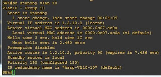
Above you can see that on SW4 I have omitted the IP address, but we can still see from the messages that HSRP works, and we can confirm it using "sh standby vlan 10":

sh standby hsrp vlan

Now we have two "sites" with working HSRP.

I will now configure the "QinQ" link (although as its not properly supported in GNS3 it is just a trunk link between the two sides).

I started by creating vlan 200, and then moving on to the trunk interfaces between SW2 and SW3. Firstly I shut down the interfaces before applying the configs and then doing a no shut on the interfaces.

The configs look like this:

configuring a trunk link

And we can see that the two sides are talking:

cisco ping

Now if we allow all VLANs over the trunk...

controlling trunk access cisco

HSRP error messages

HSRP BADVIP

Ooooh, "BADVIP" not good. Clearly we need to stop the HSRP messages from one side influencing the other side.

Lets shut down the link between SW2 and SW3, allow HSRP to recover, and figure out where to go from here.

So how do we fix this?

Blocking HSRP cross subnet traffic

We can try and stop the HSRP messages from going over our trunk, or at least from breaking the HSRP setup(s) in one of three ways:
  • Implement HSRP authentication
  • Change the HSRP group numbers on one side
  • Use an ACL

Implementing HSRP authentication

One option open to us is to use HSRP authentication.

On both switches we set up the following
SW1#conf t
SW1(config)#key chain hsrp-key
SW1(config-keychain)#key 1
SW1(config-keychain-key)#key-string 0 wtfbbq
SW1(config-keychain-key)#exit
SW1(config-keychain)#exit
SW1(config)#int vlan 10
SW1(config-if)#standby 10 authentication md5 key-chain hsrp-key
Now we can re-enable our SW2 to SW3 link and see what happens

Wireshark is seeing a lot of HSRP traffic:

Wireshark HSRP

And our switches are showing a lot of bad authentication attempts:

HSRP authentication error

But at least we don't have our VLANs getting all screwed up. 

This still isn't the optimal method, as the traffic is still being generated, and a lot of noise is being logged on our switches. So can we stop the noise on our switches, because if this is getting logged then every few seconds a log entry will be generated.

Re-numbering the standby groups

An obvious choice here is to re-number the HSRP group.

I have now changed SW3 and SW4 to use standby group 20 (instead of 10). This is just a case of entering the "no standby 10" and then setting up the HSRP group again with a new group number. This needs to be done on both switches.

Wireshark is still showing a lot of HSRP traffic, but SW1 and SW2 are not logging all the failed authentication attempts. So can we stop the traffic all together? And, showing my age, I really feel like using a picture from Airplane! after that question.


Blocking HSRP altogether
Stop HSRP traffic altogether

Using an Access Control List to block HSRP traffic

Wouldn't it be nice if we could block the multicast traffic completely across the link between the sites?

Well, what do we know about HSRP? Well, it comes in two versions, version 1 and version 2.
Version 1 uses the multicast address 224.0.0.2 and version 2 uses 224.0.0.102. Both versions have a source and destination port of 1985.

We also know that the MAC address used is 0000.0c07.ac0a.

If we try and block using the MAC address and a VACL then we could stop legitimate HSRP traffic between the switches on one site. So the solution needs to be IP based.

So we could use an ACL to block outgoing or incoming traffic to the multicast addresses used by HSRP, or block all traffic on UDP port 1985. An outgoing ACL would be the best option as it will also reduce traffic across the link.

We can see from a wireshark capture that we are using version 1 of HSRP as the multicast address is 224.0.0.2:

HSRP version 1 multicast address

The most obvious acl would be "access-list 101 deny udp any any eq 1985" and apply this to the trunk link between SW2 and SW3 outbound. Try as I might this did not work in GNS3. I had heard reports that HSRP didn't work in IOU, but it does (and you can read about how to get HSRP working on both GNS3 and IOU) so decided to give it a shot.

So anyway, the obvious acl didnt work, if I tried a direction of out I got the error:

"error ip acl configuration on 'out' direction is not supported"

And having it in an in direction didn't work as I could still see the HSRP traffic across the wire, and the HSRP was getting messages from one side interfering with the other side.

This is part if the trouble with emulated systems, it's difficult to get all the functionality you need, if you need functionality that's even slightly out of the ordinary, you either have a fight to get it to work, or it just plain won't work.

So after trying numerous ACLs and finding nothing worked I found the command "switchport block multicast" which again isn't supported by my GNS3 topology. This command has been around since at least 12.2, but apparently it's not available on GNS3, I then moved to IOU in the hope that the "switchport block multicast" command would be support, but it isn't there either. Also it looks like this is just for "unknown multicast" traffic, so probably wouldn't fit the bill anyway.

Once I was able to lab this up on real equipment (a 3750 and a 3550 for one side and a 3560 and 3550 for the other side) I was able to get some good progress. The downside of emulated equipment is that its harder (slightly) to get Wireshark sniffing going on - but that's where SPAN and RSPAN come into play. You can have a read of SPAN and RSPAN configuration.

The caveat I found was that this needs to be implemented on both sides of the link between sites.
access-list 101 deny tcp any eq 1985 host 224.0.0.2
access-list 101 deny udp any eq 1985 host 224.0.0.2
access-list 101 permit ip any any
If it's only implemented on one side only then although HSRP will recover quickly for that side, the other will still be accepting HSRP messages from the other side, and you'll see messages along the lines of:

*Mar  1 02:55:58.883: %HSRP-4-DIFFVIP1: Vlan10 Grp 10 active routers virtual IP address 10.20.1.1 is different to the locally configured address 10.10.1.1

Hence the ACL must exist on both sides, and be assigned to the link interface on the "in" direction. Sadly the out direction is not an option, but that would have been perfect for what we need. The messages still flow across the link, but are dropped according to the ACL, allowing for both sides to have identical HSRP group numbers. It's not a perfect solution as I would like to stop the traffic at source rather than destination, but it would appear to be the only option available.

Now there is the chance that the solution would actually work with emulated equipment, maybe it was down to software versions, but maybe something's just work better on real hardware (not surprising really!).

Which is the best option of the three methods?

Actually all of them, if you want a belt-and-braces approach. Just having the authentication is enough to stop the HSRP messages confusing the different sites, but will log a log of noise on the switches. Changing the standby group numbers will also help, it will certainly cut down on the noise generated by failed authentication methods, but still a lot of traffic would be crossing the link. The ACL allows us to have the same HSRP groups on each side, and (if we wanted to) the same authentication method. Due to not being able to specify the ACL in an out direction the traffic will still go across the link, but I guess that that's something I'll havr to live with.

Fun with QinQ tunnels - Part 2 (Routing different subnets)

From part one, we know that the purpose of a QinQ tunnel is to extend a VLAN across the WAN or network. But what if site 1 is connected to site 2 and they use different IP schemes (such as 10.1.250.0/24 and 10.100.250.0/24)? Well, making the two talk is actually very simple.

The way I have configured this is to set up a loopback interface on each side to emulate the different network, and set up routes between them. If you recall from part 1 I am using a 3550 on one side and a 3750 on the other.

We start by enabling IP routing on both sides:
3550(config)#ip routing
3750(config)#ip routing

Then we assign a virtual IP address to the VLAN:

         3550(config)#int vlan 501
         3550(config-if)#ip address 10.250.1.21 255.255.255.0


         3750(config)#int vlan 501
         3750(config-if)#ip address 10.250.1.20 255.255.255.0


And then we create our loopback interfaces to emulate the different networks:

        3550(config)#interface Loopback2
        3550(config-if)#ip address 10.1.250.1 255.255.255.0


        3750(config)interface Loopback2
        3750(config-if)#ip address 10.100.250.1 255.255.255.0


Lastly we set a routing statement with the destination network and the destination IP address, which is the virtual IP address of the vlan at the other side
3550(config)#ip route 10.100.250.0 255.255.255.0 10.250.1.20
3750(config)#ip route 10.1.250.0 255.255.255.0 10.250.1.21
Now we should be able to ping the loopback in each site:


QinQ routing different subnets

 Pretty neat!

Fun with QinQ tunnels - Part 1


A QinQ tunnel extends a VLAN across the network, or the internet. The usual way this is done is by having a standard VLAN in your network connecting to a QinQ tunnel in the service provider network at both ends.

This allows mutiple VLANs in your network to be encapsulated within another VLAN across the demarc boundaries, and back into your network at another site.

There are some prerequisites with setting up a QinQ, in that the MTU size must be increased to accommodate the larger packet size. You also need a switch that supports them, for this I used a 3560 and a 3750, both running Advanced IP Services, the Inside switches (in the first diagram are 3550s, and in the final diagram we used the same 3750).

The basic diagram looks like this:
QinQ tunnels basic setup


A standard Trunk port from the Inside Switch (e0/1) connects to the QinQ trunk on the provider switch (e0/1), which then connects to the other provider switch via another standard trunk (VLAN 10, e0/10 - e0/10), and finally a QinQ tunnel port on the other Provider switch (e0/1) connects to a standard trunk port (e0/1) on the other Inside switch. The dotted line shows how the switches, and the end user, see the link.

The configuration of the switches would be as follows:

Inside switch (left hand side)

vlan 4
  name Client_VLAN
vlan 5
  name Server_VLAN
vlan 6
  name Other_VLAN

int e0/1
  description **** Link to QinQ ****
  switchport trunk encapsulation dot1q
  switchport trunk allowed vlan 4,5,6
  switchport mode trunk

int e0/4
  switchport access vlan 4 

int e0/5
  switchport access vlan 5

int e0/6
  switchport access vlan 6

Provider Switch (left hand side)

system mtu 1998
system mtu jumbo 9000
vlan 10
  name QinQ_VLAN

int e0/1
  description **** QinQ VLAN ****
  switchport access vlan 10
  switchport trunk encapsulation dot1q
  switchport mode dot1q-tunnel
  no keepalive
  l2protocol-tunnel cdp
  l2protocol-tunnel stp

int e0/10
  description **** Provider to Provider link ****
  switchport trunk encapsulation dot1q
  switchport trunk allowed vlan 10
  switchport mode trunk

Provider Switch (right hand side)

system mtu 1998
system mtu jumbo 9000
vlan 10
  name QinQ_VLAN

int e0/1
  description **** QinQ VLAN ****
  switchport access vlan 10
  switchport trunk encapsulation dot1q
  switchport mode dot1q-tunnel
  no keepalive
  l2protocol-tunnel cdp
  l2protocol-tunnel stp

int e0/10
  description **** Provider to Provider link ****
  switchport trunk encapsulation dot1q
  switchport trunk allowed vlan 10
  switchport mode trunk

Inside switch (right hand side)

vlan 4
  name Client_VLAN
vlan 5
  name Server_VLAN
vlan 6
  name Other_VLAN

int e0/1
  description **** Link to QinQ ****
  switchport trunk encapsulation dot1q
  switchport trunk allowed vlan 4,5,6
  switchport mode trunk

int e0/4
  switchport access vlan 4

int e0/5
  switchport access vlan 5

int e0/6
  switchport access vlan 6


Now if you attach a laptop to the same ports on both sides and assign an IP address to both laptops (say 10.1.1.10/24 and 10.1.1.11/24) they should be able to ping each other.

The above is an in-an-ideal-world scenario. Really you just want to be able to configure standard trunk links on your equipment and have the service provider take care of all the QinQ configuration. But sometimes what you get is slightly different. And what we got was this:
QinQ tunnels advanced setup


Now our options were to either (A) purchase a new switch so we can replicate the layout in the first picture, or (B) try and find a way of having the QinQ settings and the trunk settings on the same switch. Option A would cost quite a bit of money, but is option B possible? Can a QinQ tunnel exist on the same switch as the trunk? The dangers are that it won't work due to loopguard and bpduguard. But it's worth a shot, right?

Turns out that it is, and all it takes is one little ethernet cable, now connected from port e0/1 to e0/2. Port e0/10 is then used to link up to the provider switch at the other site.

The settings for the switches on the left hand side remain the same, but what we have done is loop a cable from one port back into another port. 

QinQ tunnels using a loopback and one switch

So now all of the config for both the right hand side switches goes into the one switch (we used a 3750):

system mtu 1998
system mtu jumbo 9000

vlan 10
  name QinQ_VLAN
vlan 4
  name Client_VLAN
vlan 5
  name Server_VLAN
vlan 6
  name Other_VLAN

int e0/1
  description **** Link to QinQ ****
  switchport trunk encapsulation dot1q
  switchport trunk allowed vlan 4,5,6
  switchport mode trunk

int e0/2
  description **** QinQ VLAN ****
  switchport access vlan 10
  switchport trunk encapsulation dot1q
  switchport mode dot1q-tunnel
  no keepalive
  l2protocol-tunnel cdp
  l2protocol-tunnel stp

int e0/4
  switchport access vlan 4 

int e0/5
  switchport access vlan 5

int e0/6
  switchport access vlan 6

int e0/10
  description **** Provider to Provider link ****
  switchport trunk encapsulation dot1q
  switchport trunk allowed vlan 10
  switchport mode trunk

Traffic will (effectively) come in on e0/1, get encapsulated in e0/2 and traverse to the other side via e0/10, again we tested via ping and all was good.

So it turns out that you can have your QinQ trunk and the VLAN trunk living on the same switch.

Part two answers the question "Can we route different subnets across a QinQ link?"