Showing posts with label VLANs. Show all posts

The BIG lab - Part 1 - Trunking, EtherChannel and Load-Balancing

I kind of feel that I really need to spend more time on my studies at the moment. So while the boys are down for their afternoon nap (but not sleeping) it's a good chance to get some work done.

In the real lab there will be a fairly large selection of switches and routers, and although you will have a number of specific tasks to complete both for the troubleshooting portion and the configuration portion it's important to understand that one task can greatly impact on another.

So instead of having little posts concentrating on one particular topic I have decided to make a number of posts but all sharing the same topology so that the impact of one design decision can be shown throughout the network.

So let's have a look at the things that I want to cover, and start building our topology.

Starting at the top of the CCIE exam topics we can cover:
Now you will have to excuse my drawing skills, I am using a Wacom Bamboo tablet and still getting used to it, but I think we'll end up with something like this:


So we have a number of routing protocols, a bit of frame relay, some trunking, etherchannel, well throw in some dialup technology, tunnelling and some IPv6 as well, and lets throw in some VTP for good measure. I think that this series will be very organic and will change and grow as we progress.

Let's start creating the netmap, as always I start by numbering the devices from left to right. and working out the connections from there. Apart from getting the R10 to SW1 interfaces round the wrong way, once I corrected it I ended up with this:


Cisco IOU netmap


If you are interested, the netmap looks like this:

1:0/0 2:0/0
2:0/1 3:0/0
2:0/2 4:0/0
4:0/1 5:0/0
5:0/1 6:0/0
6:0/1 7:0/1
4:0/2 8:0/0
5:0/2 9:0/0
8:0/1 9:0/1
8:0/2 10:1/0
10:0/1 11:1/1
11:0/0 12:0/0
11:0/1 12:0/1
11:0/2 13:1/0
13:0/0 14:0/0
13:0/1 14:0/1
12:1/0 14:1/0

So lets start at the top of our list and work our way down. I might just cover some trunking today as the kids have not gone to sleep, but they did get up at 8:30 this morning instead of their usual 7am, so it's not surprising really.

Switch basic configuration

Lets start by setting up a VTP domain and have the switches as either a master or a client, along with some different VLANs. If the switches support it we might even get to do some HSRP, but I am not sure if they do. To be honest I don't even know if they do etherchannel, but I guess we'll find out whether this is a limitation of the software (IOU) or not.

Trunking - VTP and 802.1Q trunks

We'll start by creating a bunch of VLANs on SW1, and set up VTP.

So in SW1 we set up a bunch of VLANs, (10,20,30, and 40 using the "vlan 10" etc command), and then set the vtp mode to server (which is the default but I still like to know that I have set it manually), and set the domain from null to 802101:


VTP Server setup cisco switch

Now we can set up a trunk to SW3, we will only use 802.1Q for our trunks because the other trunking protocol (ISL) isnt used much anymore.

We arnt going to do anything fancy with our trunk (at least not yet) so its a basic configuration:


802.1Q trunking on a Cisco Switch

And I have set SW3 as a VTP client for the 802101 domain:


Cisco switch vtp client

Usually its worth heading back to the server to make an amendment to the VLAN database on the server to force it to send the updates to the clients. So I added VLAN 50 on to SW1, and then running "sh vtp status" on SW3 I can see that the two are talking:


cisco vtp status

OK, so thats the link between SW1 and three done. Lets set up SW2 and 4 in the same way:


setting up vtp client and trunking


setting up vtp client and trunking

Now we can set up our etherchannel links between SW1 and SW2 (PAgP) and between SW3 and SW4 (LACP).

EtherChannel - Setting up PAgP and LACP

I said earlier that I wasn't going to bother with ISL for our trunks because it's no longer used much, well the same does not hold true for the etherchannel protocols. Both are used and both have a very good chance of being included in the exam. Therefore I will be doing both. PAgP (Port Aggregation Protocol) is the Cisco standard, whilst LACP is the industry standard. 

For any type of etherchannel to work the settings on the interfaces within the port-channel group must match identically, so you can't mix duplex or speed for example. I prefer to set mine up using the interface range command ("interface range ethernet 0/0 - 1"). First I shut down the interfaces (you don't have to, I just like to know I have got everything set before I try and bring the port-channel up), then set them up as trunks, adding them to the port-channel group 1. I have set SW1 as "auto" for PAgP:


pagp etherchannel cisco

and SW2 as "desirable" for PAgP:


setting up vtp client and trunking

Lastly i did a "no shut" on the interfaces. 

The basic config is:

SW(config)#interface range ethernet 0/0 - 1
SW(config-if-range)#shut
SW(config-if-range)#switchport trunk encapsulation dot1q
SW(config-if-range)#switchport mode trunk
SW(config-if-range)#channel-protocol <protocol>
SW(config-if-range)#channel-group 1 mode <mode>
SW(config-if-range)#no shut

Lets have a look at the last two lines in a bit more detail.

We start by setting the protocol, this is either PAgP or LACP:


cisco etherchannel

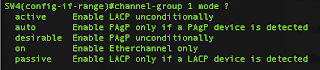
And then we set the mode


cisco etherchannel channel group mode

Both sides could have been made desirable for PAgP, or active for LACP, and would have formed a channel-group, but if both were set to auto (PAgP) or passive (LACP) then no channel-group would form, as neither would be actively seeking to make a channel-group.

Here is a sh run from both sides:


port channels and load balancing


port channels and load balancing

And as if by magic if we do a "sh vlan" on SW2 we can see that by the magic of VTP we have our VLANs now:


vtp in action

Now let's turn our attention to SW3 and SW4.

There isn't much different between the setups, the same commands have been used to create the trunk links:


port channels and load balancing


port channels and load balancing

And lastly on SW4 we check to see if our VLANs are all present and correct:


vtp over port channel
And they are.

From now on our port-channel operates pretty much just like any normal interface, We can do a "sh int po 1" and see the following:


show port channel

The interesting thing here is that we can see the members of the port-channel (in the last line).

We can also check on our neighbor switches:


port channels and load balancing neighbor

Load-balancing

I did set up src-dst-mac load balancing on SW1 and SW2, it is a global statement 


port-channel load-balancing
I chose src-dst-mac


port-channel-load-balancing

Load balancing is pretty simple really.

And that about covers it for today. The boys didn't sleep at all this afternoon, so now its half past eight at night and its time for a snack. 

Next up we'll cover the PPP link between R1 and R2.

Fun with QinQ tunnels - Part 2 (Routing different subnets)

From part one, we know that the purpose of a QinQ tunnel is to extend a VLAN across the WAN or network. But what if site 1 is connected to site 2 and they use different IP schemes (such as 10.1.250.0/24 and 10.100.250.0/24)? Well, making the two talk is actually very simple.

The way I have configured this is to set up a loopback interface on each side to emulate the different network, and set up routes between them. If you recall from part 1 I am using a 3550 on one side and a 3750 on the other.

We start by enabling IP routing on both sides:
3550(config)#ip routing
3750(config)#ip routing

Then we assign a virtual IP address to the VLAN:

         3550(config)#int vlan 501
         3550(config-if)#ip address 10.250.1.21 255.255.255.0


         3750(config)#int vlan 501
         3750(config-if)#ip address 10.250.1.20 255.255.255.0


And then we create our loopback interfaces to emulate the different networks:

        3550(config)#interface Loopback2
        3550(config-if)#ip address 10.1.250.1 255.255.255.0


        3750(config)interface Loopback2
        3750(config-if)#ip address 10.100.250.1 255.255.255.0


Lastly we set a routing statement with the destination network and the destination IP address, which is the virtual IP address of the vlan at the other side
3550(config)#ip route 10.100.250.0 255.255.255.0 10.250.1.20
3750(config)#ip route 10.1.250.0 255.255.255.0 10.250.1.21
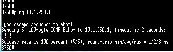
Now we should be able to ping the loopback in each site:


QinQ routing different subnets

 Pretty neat!

Fun with QinQ tunnels - Part 1


A QinQ tunnel extends a VLAN across the network, or the internet. The usual way this is done is by having a standard VLAN in your network connecting to a QinQ tunnel in the service provider network at both ends.

This allows mutiple VLANs in your network to be encapsulated within another VLAN across the demarc boundaries, and back into your network at another site.

There are some prerequisites with setting up a QinQ, in that the MTU size must be increased to accommodate the larger packet size. You also need a switch that supports them, for this I used a 3560 and a 3750, both running Advanced IP Services, the Inside switches (in the first diagram are 3550s, and in the final diagram we used the same 3750).

The basic diagram looks like this:
QinQ tunnels basic setup


A standard Trunk port from the Inside Switch (e0/1) connects to the QinQ trunk on the provider switch (e0/1), which then connects to the other provider switch via another standard trunk (VLAN 10, e0/10 - e0/10), and finally a QinQ tunnel port on the other Provider switch (e0/1) connects to a standard trunk port (e0/1) on the other Inside switch. The dotted line shows how the switches, and the end user, see the link.

The configuration of the switches would be as follows:

Inside switch (left hand side)

vlan 4
  name Client_VLAN
vlan 5
  name Server_VLAN
vlan 6
  name Other_VLAN

int e0/1
  description **** Link to QinQ ****
  switchport trunk encapsulation dot1q
  switchport trunk allowed vlan 4,5,6
  switchport mode trunk

int e0/4
  switchport access vlan 4 

int e0/5
  switchport access vlan 5

int e0/6
  switchport access vlan 6

Provider Switch (left hand side)

system mtu 1998
system mtu jumbo 9000
vlan 10
  name QinQ_VLAN

int e0/1
  description **** QinQ VLAN ****
  switchport access vlan 10
  switchport trunk encapsulation dot1q
  switchport mode dot1q-tunnel
  no keepalive
  l2protocol-tunnel cdp
  l2protocol-tunnel stp

int e0/10
  description **** Provider to Provider link ****
  switchport trunk encapsulation dot1q
  switchport trunk allowed vlan 10
  switchport mode trunk

Provider Switch (right hand side)

system mtu 1998
system mtu jumbo 9000
vlan 10
  name QinQ_VLAN

int e0/1
  description **** QinQ VLAN ****
  switchport access vlan 10
  switchport trunk encapsulation dot1q
  switchport mode dot1q-tunnel
  no keepalive
  l2protocol-tunnel cdp
  l2protocol-tunnel stp

int e0/10
  description **** Provider to Provider link ****
  switchport trunk encapsulation dot1q
  switchport trunk allowed vlan 10
  switchport mode trunk

Inside switch (right hand side)

vlan 4
  name Client_VLAN
vlan 5
  name Server_VLAN
vlan 6
  name Other_VLAN

int e0/1
  description **** Link to QinQ ****
  switchport trunk encapsulation dot1q
  switchport trunk allowed vlan 4,5,6
  switchport mode trunk

int e0/4
  switchport access vlan 4

int e0/5
  switchport access vlan 5

int e0/6
  switchport access vlan 6


Now if you attach a laptop to the same ports on both sides and assign an IP address to both laptops (say 10.1.1.10/24 and 10.1.1.11/24) they should be able to ping each other.

The above is an in-an-ideal-world scenario. Really you just want to be able to configure standard trunk links on your equipment and have the service provider take care of all the QinQ configuration. But sometimes what you get is slightly different. And what we got was this:
QinQ tunnels advanced setup


Now our options were to either (A) purchase a new switch so we can replicate the layout in the first picture, or (B) try and find a way of having the QinQ settings and the trunk settings on the same switch. Option A would cost quite a bit of money, but is option B possible? Can a QinQ tunnel exist on the same switch as the trunk? The dangers are that it won't work due to loopguard and bpduguard. But it's worth a shot, right?

Turns out that it is, and all it takes is one little ethernet cable, now connected from port e0/1 to e0/2. Port e0/10 is then used to link up to the provider switch at the other site.

The settings for the switches on the left hand side remain the same, but what we have done is loop a cable from one port back into another port. 

QinQ tunnels using a loopback and one switch

So now all of the config for both the right hand side switches goes into the one switch (we used a 3750):

system mtu 1998
system mtu jumbo 9000

vlan 10
  name QinQ_VLAN
vlan 4
  name Client_VLAN
vlan 5
  name Server_VLAN
vlan 6
  name Other_VLAN

int e0/1
  description **** Link to QinQ ****
  switchport trunk encapsulation dot1q
  switchport trunk allowed vlan 4,5,6
  switchport mode trunk

int e0/2
  description **** QinQ VLAN ****
  switchport access vlan 10
  switchport trunk encapsulation dot1q
  switchport mode dot1q-tunnel
  no keepalive
  l2protocol-tunnel cdp
  l2protocol-tunnel stp

int e0/4
  switchport access vlan 4 

int e0/5
  switchport access vlan 5

int e0/6
  switchport access vlan 6

int e0/10
  description **** Provider to Provider link ****
  switchport trunk encapsulation dot1q
  switchport trunk allowed vlan 10
  switchport mode trunk

Traffic will (effectively) come in on e0/1, get encapsulated in e0/2 and traverse to the other side via e0/10, again we tested via ping and all was good.

So it turns out that you can have your QinQ trunk and the VLAN trunk living on the same switch.

Part two answers the question "Can we route different subnets across a QinQ link?"

VTP - VLAN Trunking Protocol (1.20)

Configuring VLANs on one or two switches is easy enough, but as the scope of the VLANs increases managing each switch's VLANs individually can become an administrative headache, and prone to mistakes and inconsistencies. Therefore a VLAN management protocol can make this much, much easier.

VTP is one of a couple of VLAN management protocols, the others being GARP VLAN Registration Protocol (GVRP) these are defined in 802.1D (GARP) and 802.1Q (clause 11) for GVRP. These others are not currently supported by Cisco and are therefore not part of the Switch exam, or the CCIE exam.

VTP manages the addition, deletion and renaming of VLANs across the network from a centralised point.

VTP uses domains (areas with common VLAN requirements). A switch can only belong to one VTP domain.

To participate in a VTP domain each switch must be in one of the following modes:

1. Server mode - this has full control over VLAN creation, deletion and modification, this is the default mode for switches.
2. Client mode - cannot create, change or delete and VLANs. Clients listen to VTP advertisements from other switches and modify their own VLAN configuration. Also acts as a relay, forwarding VTP information to other switches.
3. Transparent mode - does not participate in VTP, and does not advertise its own VLAN configuration. With VTP version 1 it does not relay VTP information from other switches unless the VTP domain names and numbers match. In VTP version 2 they can still act as relays regardless of the VTP domain name.

VTP advertisements are sent using multicast and reference an index called the configuration revision number. The revision number starts at zero and increments by one with any change, at which point the update is sent to all VTP listening switches.

New switches should always be cleared of all VTP information before being introduced into the network.

VTP configuration

Head back into the PacketTracer lab we created earlier and add the following:

Management domain:

switch0(config)# vtp domain vtptest

switch1(config)# vtp domain vtptest

Mode:

switch0(config)# vtp mode server
switch0(config)# vtp version 2
switch0(config)# vtp password vtppassword

switch1(config)# vtp mode client
switch1(config)# vtp version 2

switch1(config)# vtp password vtppassword

Setting a VTP server

Setting a VTP client

Now we can add a couple of VLANs - so on Switch0 add VLANs 4 and 5, then do a sh vlan on Switch1

Create a VLAN

Without adding anything to Switch1 you should see 

show vlan

Running a show vtp status on switch0 you should see

show vtp status

VTP Pruning

VTP Pruning makes more efficient use of trunk bandwidth by reducing unnecessary flooded traffic.

To implement this it is just a case of typing "vtp pruning" in config mode. But this is not supported in PacketTracer, at least not in the version I am running. It might be supported in future releases.

switch(config)# vtp pruning

Once this is added on server it is also enabled on the VTP clients.

Troubleshooting VTP

Check the mode if updates are not being received - make sure not in transparent.
Makes sure at least one switch is set as the server.
Make sure trunks are used as VTP advertisement are only sent over trunk links.
Make sure VTP domain name is identical across all switches.
VTP versions should be compatible.
Passwords should match for VTP.


VLANs and Trunks (1.20)

To those of you who have passed the CCNA certification training, then this should not be anything new, but it's good to have a recap, especially as it is clearly stated on the CCIE syllabus.

VLANs are a way of segmenting your traffic into business or geographic boundaries, a logical network segment. A VLAN introduces a separate broadcast domain - so broadcasts will not cross VLAN boundaries.

There are two types of VLANs, static or dynamic:


Static VLANs

Static VLANs are port based. Set up is easy.

Open up Packet tracer and drag two switches and two workstations onto it. I have used different switches (a 2960 and a 2950)

On the switches enter the following

Switch0(config)# vlan 2
Switch0(config-vlan)# name VLAN2

Now connect the fastethernet 0/2 port to the switches and enter this: 

Switch0(config)# interface FastEthernet0/2
Switch0(config-if)# switchport mode access
Switch0(config-if)# switchport access vlan 2

Give the workstations ip addresses of 10.0.0.12/24 and 10.0.0.13/24

Dynamic 

Dynamic VLANs are based on MAC addresses not covered as part of the CCNP Switch, and neither are they covered in the CCIE exam.

Deploying VLANs

There are two ways to deploy VLANs across the infrastructure, End-to-End or Local VLANs

End-to-End vlans 

Also know as campuswide VLANs, these span the entire fabric of a network, they are positioned to support maximum flexibility and mobility of end users and follow the 80/20 rule, whereby 80% of traffic is within the local workgroup, and 20% is destined for outside networks.

End-to-End VLANs are more difficult to manage than Local VLANs due to the increased broadcasts around the network

Local VLANs 

These are based on geographic needs and follows the 20/80 rule - 20% is local traffic, 80% is traffic that wiull traverse the core layer. More commonly used than end-to-end.

Trunking

A trunk is used to transport many VLANs between switches, frames are tagged with an ID corresponding to the VLAN number and there are two types of trunk - ISL and 802.1Q.

ISL which is proprietary to Cisco, but is now deprecated in favor of 802.1Q. ISL encapsulates each frame between a header and trailer.

802.1Q is the industry standard. Tags are embedded within the frame, and it uses a concept called the "native VLAN". Frames beloging to this VLAN are not encapsulated with any tagging information.

Trunks can be forcefully set or allowed to form under their own default settings. This uses DTP (Dynamic Trunking Protocol) and it negotiates a common trunking mode between two switches. A trunk link can be negotiated between two switches only if they belong to the same VTP domain (VLAN Trunking Protocol covered next), or if both switches do not have the VTP domain specified (i.e NULL domain). If the two switches are in different VTP domains and trunking is required then the trunk links must be set to On or Negotiate mode.

The configuration is as follows:

Switch(config)# interface type mod/port 
Switch(config-if)# switchport trunk encapsulation {isl | dot1q | negotiate} 
Switch(config-if)# switchport trunk native vlan vlan-id
Switch(config-if)# switchport trunk allowed vlan {vlan-list | all | {add | except | remove} vlan-list}
Switch(config-if)# switchport mode {trunk | dynamic {desirable | auto}}

There are three trunking modes:

1: trunk - permanent trunking mode (on). 
2: dynamic desirable - (the default) The port actively tries to convert the link to trunking and asks the far end to bring up a trunk. If the far end is set to trunk, dynamic desirable or auto then a trunk is formed.
3: dynamic auto - the port can be converted into a trunk if the other side actively asks for it. The other side must be set as trunk or dynamic desirable. if both sides are set to auto a trunk is not formed.

DTP packets are set every 30 seconds. To stop these (i.e. if unnecessary bandwidth is an issue, or just to follow best-practice) set the trunk ports to "switchport nonegotiate"

Returning to our Packet Tracer example configure a link between fastEthernet0/1 on each switch. Your PacketTracer screen should look like this:

Setting up trunk ports

Configure the first switch like this: 

switch0(config)# int fastethernet 0/1
switch0(config-if)# switchport trunk encapsulation dot1q
switch0(config-if)# switchport trunk native vlan 2
switch0(config-if)# switchport trunk allowed vlan 100-200
switch0(config-if)# switchport mode trunk 
switch0(config-if)# switchport nonegotiate

If the other side's native VLAN settings do not match then you should see this message:

VLAN mismatch error message

OK, now did you have any issues with the commands? You should have found that the encapsulation command did not work. This is because ISL is being deprecated in favour of 802.1Q and Cisco has started to remove the ISL option from its line up.

Now configure the other switch in the same way as the first.

Issuing a sh interfaces trunk you can see:

sh interfaces trunk

You should be able to ping from one PC to another across the trunk.

Save this PacketTracer lab as we will be expanding on it later on.

Troubleshooting

Make sure that the VLANs re where they should be (sh vlan id 2)
Make sure that the trunking parameters are set (trunk, negotiated or nonegotiate)
Make sure that the trunks are talking the same language (802.1Q, or ISL)
Make sure that the native VLAN is set when using 801.1Q
Make sure that the Allowed VLANs match on both sides.

Commands:

sh interface trunk (shown above)
sh dtp <int> to see DTP packets
sh interface <int> switchport 

sh int switchport


Next we'll move on to VTP.