Cisco ASA Firewall Netflow Configuration

Today we will be having a look at Cisco Netflow configuration on an ASA firewall. We will be using PRTG Network Monitoring, from Paessler, which is a free netflow collector and analyzer that supports 10 sensors, which you can download from here.

Installing PRTG is very straight forward, it's all point and click, so I will save you all the obvious screenshots and dive right in.

What is Netflow?

Netflow was designed by Cisco to collect IP network traffic. This data can then be analysed for source, destination, protocol, class of service etc, and uses a flow cache, Flow Collector and a Flow analyser to present the data in an understandable way.

Cisco ASA Netflow configuration

Firstly you'll need at least ASA 8.2.1, and ASDM 6.2.1. I am using ASA version 9.0(3) and ASDM version 7.1(6).

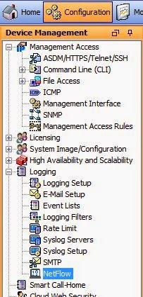
The Netflow settings in ASDM are located in Configuration > Logging > NetFlow

Cisco Netflow Configuration

Click on Add and specify the IP address of the server running the Netflow software, and specify a port of 2055.

Add Netflow Collector Cisco ASA

The next step is to start throwing all of our traffic at the netflow collector. To do this we must set up a service policy rule.

Firewall > Service Policy Rules and click on Add.

Create Service Policy Cisco ASA

Select "Global - applies to all interfaces" and keep the default name of global-class

Netflow service policy

Select Source and Destination IP addresses (uses ACL)  and click Next

Netflow Access Control List

For the Source and Destination select "any", and for the service select ip (I did also add icmp, icmp/echo and icmp/echo-reply)

ASA ACL for Netflow Cisco

On the next page select the NetFlow tab, click on add and select the Netflow collector IP to the one we configured in the first step, making sure that we click Send. Click OK.

Netflow Configuration Cisco

Lastly click on "Finish"

Finisherd Netflow Configuration

We now need to set up PRTG.

Creating a Netflow sensor on PRTG for Cisco ASAs

Hopefully your firewall should have already been picked up through its own ping tests. If not click on Devices and select add a device. We can either create a new group, or add it to an exisiting group. Give the new device a meaning full name, and then you can click on Add Sensor.

Create ASA sensor for Netflow PRTG

Select NetFlow V9, and click on "Add This"

Give the sensor a name, and set the "Receive NetFlow Packets on UDP Port" to the same port we configured on the ASA (2055). Set the sender IP to the ASAs interface IP address, and set the "Active Flow Timeout (Minutes) to something (I have used 30). To get some decent data I also set the channel configuration for Infrastructure to "Detail":

Netflow Sensor ASA

Give it a little time for the collector to get some data, five minutes or so should do, and hopefully you should start seeing some data:

Netflow overview PRTG

 (the above screenshot references a different sensor number to the one above it - but don't worry about that - I just set up additional sensors to get a screenshot).

You can also drill down into the sensor and see the top protocols:

Netflow specific data PRTG
It's pretty quick to start getting some good information out of your firewalls using NetFlow, and PRTG. 

There are a number of Netflow systems out there, if you are good with Linux then there are free ones available.

netflow is a very powerful, and potentially cheap way to have a fully fledged network monitoring system.
How NOT to do an ASA failover pair upgrade successfully

How NOT to do an ASA failover pair upgrade successfully

Firstly let me say that I don't know what's up with me today. It's either down to not enough coffee, or just being plain tired. Either way this is a shameful post.

I have done ASA upgrades numerous times, both on single units and in failover pairs. They all went fine. Today though my brain just isn't engaging in order to make something that's second nature, a straight forward process.

So when you do an ASA upgrade the process is to copy the new files (the ASA bin file and ASDM bin file) to the firewalls disk.

I did this on the primary through ASDM, then went and changed the boot order and the ASDM image.
asa# configure terminal
asa(config)# boot system disk0:/asa915-smp-k8.bin
asa(config)# asdm image disk0:/asdm-716.bin
asa(config)#
I then found that I could not copy the files to the secondary ASA. FTP would not work, TFTP would not work, both had different errors, probably due to antivirus/firewall or something on the Windows box, and I could not get in to ASDM on the public IP or the inside address of the secondary.

I tried to fail over in the hope that if it was the primary I could get in again, but same issue.

Much cursing later I realised that if I changed the boot order back to the original settings then I could again access the secondary through ASDM.

Once the newer ASA and ASDM image were loaded onto the secondary, I set the boot order on the primary to the later version (9.1.5), and set the ASDM image version (7.1.6).

All is good, versions match. Let's failover.

After failover the secondary came up and the version was still at the same as before (9.1.3), and the ASDM was at 7.1.4.

I checked the boot order on the secondary, looked fine, all set as I wanted. Files were still present, so what was wrong? Checked running config - again all looked ok.

Stupidly I had not saved the config on the primary - so when the secondary booted up the startup config referenced the old versions, but once it was up the failover process sent the primary's running-config onto the standby, which is why it all looked fine.

After a bit more cursing and wanting to kick myself I saved the config, reloaded the standby, which then came up in the right version, failed over and reloaded the other ASA.

Both are now on the newer versions of ASA and ASDM, and I feel like a fool.

How to properly do an ASA failover pair upgrade

Copy the files to BOTH ASAs - its easy to do with ASDM - Tools > File Management and copy them over.

Set the boot system image and the asdm image (as above)
Then SAVE the config (copy run start)

Reload the standby unit:
asa#failover reload-standby
Make sure it all comes up ok, check failover looks fine
asa#sh failover | i Version"
Version: Ours 9.1(3), Mate 9.1(5)
Make the primary unit the standby, you can do this from the primary with the command:
asa#no failover active
And then reload the standby using the reload-standby command again.
Lastly check failover again:
asa#sh failover | i Version"
Version: Ours 9.1(5), Mate 9.1(5)
If all goes well it should be completed within about 15 minutes at the most! If you are using SSH then you might need to reconnect after the failover.

If you need me I'll be standing in the corner...

BGP Load Balancing with Cisco IOS and Junos

Today we are going to do some BGP load balancing between a Cisco router and a Juniper router.

We have a very simple topology:


The Juniper router (JUNOS1) is called NewYork and the Cisco router (R1) is called London.

We have two connections between them 1.1.1.1/24 on the Juniper to 1.1.1.2/24 on the Cisco, and 2.2.2.1 on the Juniper to 2.2.2.2 on the Cisco. We will be using AS 65000 for the BGP AS.

For the Juniper basic configuration please check out these two posts:

Juniper router emulation in GNS3
Basic Juniper Router commands

What is BGP Load Balancing?

Load balancing can use two or more connections to send data to the same destination. Load balancing in BGP requires that we enable multi-pathing, so that the router knows that it can use more than one path at a time.

We will start with the basic BGP configuration and from there advertise a loopback network on each side, then we will set up multi-pathing.

Cisco IOS BGP setup

I won't explain all the Cisco steps as they shouldn't be anything new - but there are links to my book here. Shameless plug I know!
London(config)#router bgp 65000
London(config-router)#neighbor 1.1.1.1 remote-as 65000
London(config-router)#neighbor 2.2.2.1 remote-as 65000
London(config-router)#exit
London(config)#exit
London#

Juniper JunOS BGP setup

For the JunOS set up we will create the BGP AS under routing options, and then create a group called Cisco to add the two peerings to the Cisco router to, setting the AS number to match our own, and the type to be internal (iBGP).
root@NewYork> configure
Entering configuration mode

[edit]
root@NewYork# set routing-options autonomous-system 65000
root@NewYork# set protocols bgp group Cisco neighbor 1.1.1.2
root@NewYork# set protocols bgp group Cisco neighbor 2.2.2.2
root@NewYork# set protocols bgp group Cisco peer-as 65000
root@NewYork# set protocols bgp group Cisco type internal
root@NewYork# commit
commit complete

[edit]
root@NewYork#
At this stage our BGP peers should come up:
London#
*Apr 21 13:19:18.087: %BGP-5-ADJCHANGE: neighbor 1.1.1.1 Up
London#
*Apr 21 13:19:22.227: %BGP-5-ADJCHANGE: neighbor 2.2.2.1 Up
London#
We can confirm this by looking at the bgp neighbors on the NewYork router:
root@NewYork> show bgp neighbor
Peer: 1.1.1.2+46617 AS 65000   Local: 1.1.1.1+179 AS 65000
  Type: Internal    State: Established    Flags: 
  Last State: OpenConfirm   Last Event: RecvKeepAlive
  Last Error: None
  Options: 
  Holdtime: 90 Preference: 170
  Number of flaps: 0
  Peer ID: 2.2.2.2         Local ID: 1.1.1.1      Active Holdtime: 90
  Keepalive Interval: 30         Peer index: 0   
  BFD: disabled, down
  NLRI for restart configured on peer: inet-unicast
  NLRI advertised by peer: inet-unicast
  NLRI for this session: inet-unicast
  Peer supports Refresh capability (2)
  Stale routes from peer are kept for: 300
  Peer does not support Restarter functionality
  Peer does not support Receiver functionality
  Peer supports 4 byte AS extension (peer-as 65000)
  Peer does not support Addpath
  Table inet.0 Bit: 10000
    RIB State: BGP restart is complete
    Send state: in sync
    Active prefixes:              1
    Received prefixes:            1     
    Accepted prefixes:            1
    Suppressed due to damping:    0
    Advertised prefixes:          0
  Last traffic (seconds): Received 15   Sent 22   Checked 40  
  Input messages:  Total 8 Updates 2  Refreshes 0  Octets 226
  Output messages: Total 7 Updates 0  Refreshes 0  Octets 173
  Output Queue[0]: 0

Peer: 2.2.2.2+179 AS 65000     Local: 2.2.2.1+51595 AS 65000
  Type: Internal    State: Established    Flags: 
  Last State: OpenConfirm   Last Event: RecvKeepAlive
  Last Error: None
  Options: 
  Holdtime: 90 Preference: 170
  Number of flaps: 0
  Peer ID: 2.2.2.2         Local ID: 1.1.1.1      Active Holdtime: 90
  Keepalive Interval: 30         Peer index: 1   
  BFD: disabled, down
  NLRI for restart configured on peer: inet-unicast
  NLRI advertised by peer: inet-unicast
  NLRI for this session: inet-unicast
  Peer supports Refresh capability (2)
  Stale routes from peer are kept for: 300
  Peer does not support Restarter functionality
  Peer does not support Receiver functionality
  Peer supports 4 byte AS extension (peer-as 65000)
  Peer does not support Addpath
  Table inet.0 Bit: 10000
    RIB State: BGP restart is complete
    Send state: in sync
    Active prefixes:              0
    Received prefixes:            1
    Accepted prefixes:            1
    Suppressed due to damping:    0
    Advertised prefixes:          0
  Last traffic (seconds): Received 13   Sent 21   Checked 35  
  Input messages:  Total 5 Updates 2  Refreshes 0  Octets 135
  Output messages: Total 6 Updates 0  Refreshes 0  Octets 154
  Output Queue[0]: 0

root@NewYork> 

Advertising BGP prefixes in Cisco IOS and Juniper JunOS

Now we can add our loopback interfaces, and advertise them into BGP:
London(config)#int lo0
London(config-if)#ip add 172.20.1.1 255.255.255.0
London(config-if)#router bgp 65000
London(config-router)#network 172.20.1.0 mask 255.255.255.0
London(config-router)#
NewYork sees the route coming from both peering sessions, it prefers the one with the lower IP address (denoted by a *):
root@NewYork> show route
inet.0: 5 destinations, 6 routes (5 active, 0 holddown, 0 hidden)
+ = Active Route, - = Last Active, * = Both

1.1.1.0/24         *[Direct/0] 01:08:36
                    > via em0.0
1.1.1.1/32         *[Local/0] 01:08:36
                      Local via em0.0
2.2.2.0/24         *[Direct/0] 01:08:36
                    > via em1.0
2.2.2.1/32         *[Local/0] 01:08:36
                      Local via em1.0
172.20.1.0/24      *[BGP/170] 00:01:20, MED 0, localpref 100
                      AS path: I
                    > to 1.1.1.2 via em0.0
                    [BGP/170] 00:01:20, MED 0, localpref 100
                      AS path: I
                    > to 2.2.2.2 via em1.0

root@NewYork>
Now let's add a loopback interface on the NewYork router and advertise it in BGP as well. The process isn't exactly as straight forward in JunOS, all advertisement is done through policy statements, which is then used to export (advertise to BGP neighbors) based on the specified group:
root@NewYork# set int lo0 unit 0 family inet address 192.168.1.1/24
root@NewYork# edit policy-options                                      

[edit policy-options]
root@NewYork# set policy-statement ADVERTISE_LO0 from interface lo0    
root@NewYork# set policy-statement ADVERTISE_LO0 then accept 

[edit policy-options]
root@NewYork# exit 

[edit]
root@NewYork# set protocols bgp group Cisco export ADVERTISE_LO0       

[edit]
root@NewYork# commit 
commit complete

[edit]
root@NewYork# 

And if all is well then the London router should see the new prefix:
London#sh ip route | beg Gate
Gateway of last resort is not set

      1.0.0.0/8 is variably subnetted, 2 subnets, 2 masks
C        1.1.1.0/24 is directly connected, GigabitEthernet1/0
L        1.1.1.2/32 is directly connected, GigabitEthernet1/0
      2.0.0.0/8 is variably subnetted, 2 subnets, 2 masks
C        2.2.2.0/24 is directly connected, GigabitEthernet2/0
L        2.2.2.2/32 is directly connected, GigabitEthernet2/0
      172.20.0.0/16 is variably subnetted, 2 subnets, 2 masks
C        172.20.1.0/24 is directly connected, Loopback0
L        172.20.1.1/32 is directly connected, Loopback0
B     192.168.1.0/24 [200/0] via 1.1.1.1, 00:00:15
London#
It does, again choosing the router with the lower IP address. Now let's set up load balancing.

Enabling load balancing for BGP in Cisco IOS

Enabling load balancing in BGP on Cisco IOS is as simple as enabling the maximum-paths option.
London(config-router)#maximum-paths ibgp 2
London(config-router)#do sh ip route | beg Gate
Gateway of last resort is not set

      1.0.0.0/8 is variably subnetted, 2 subnets, 2 masks
C        1.1.1.0/24 is directly connected, GigabitEthernet1/0
L        1.1.1.2/32 is directly connected, GigabitEthernet1/0
      2.0.0.0/8 is variably subnetted, 2 subnets, 2 masks
C        2.2.2.0/24 is directly connected, GigabitEthernet2/0
L        2.2.2.2/32 is directly connected, GigabitEthernet2/0
      172.20.0.0/16 is variably subnetted, 2 subnets, 2 masks
C        172.20.1.0/24 is directly connected, Loopback0
L        172.20.1.1/32 is directly connected, Loopback0
B     192.168.1.0/24 [200/0] via 2.2.2.1, 00:00:02
                     [200/0] via 1.1.1.1, 00:00:02
London(config-router)#do sh ip bgp
BGP table version is 5, local router ID is 2.2.2.2
Status codes: s suppressed, d damped, h history, * valid, > best, i - internal,
              r RIB-failure, S Stale, m multipath, b backup-path, x best-external, f RT-Filter
Origin codes: i - IGP, e - EGP, ? - incomplete

   Network          Next Hop            Metric LocPrf Weight Path
*> 172.20.1.0/24    0.0.0.0                  0         32768 i
*mi192.168.1.0      1.1.1.1                       100      0 i
*>i                 2.2.2.1                       100      0 i
London(config-router)#
So our London router has now installed two paths into the routing table, courtesy of the maximum-paths command. Let's configure the same on the NewYork router.

Enabling load balancing for BGP in Juniper JunOS

Similarly to the Cisco IOS all we need to do with JunOS is to enable multipath under our BGP peer group:
root@NewYork# edit protocols bgp group Cisco
[edit protocols bgp group Cisco]
root@NewYork# set multipath 

[edit protocols bgp group Cisco]
root@NewYork# exit 

[edit]
root@NewYork# commit 
commit complete

[edit]
root@NewYork# exit 
Exiting configuration mode

root@NewYork> show route 172.20.1.0    

inet.0: 7 destinations, 8 routes (7 active, 0 holddown, 0 hidden)
+ = Active Route, - = Last Active, * = Both

172.20.1.0/24   *[BGP/170] 00:24:56, MED 0, localpref 100, from 1.1.1.2
                   AS path: I
                   to 1.1.1.2 via em0.0
                 > to 2.2.2.2 via em1.0
                 [BGP/170] 00:11:42, MED 0, localpref 100
                   AS path: 
                 > to 2.2.2.2 via em1.0

root@NewYork> show route 172.20.1.0 detail 

inet.0: 7 destinations, 8 routes (7 active, 0 holddown, 0 hidden)
172.20.1.0/24 (2 entries, 1 announced)
        *BGP    Preference: 170/-101
                Next hop type: Indirect
                Address: 0x9408078
                Next-hop reference count: 2
                Source: 1.1.1.2
                Next hop type: Router, Next hop index: 520
                Next hop: 1.1.1.2 via em0.0
                Next hop type: Router, Next hop index: 554
                Next hop: 2.2.2.2 via em1.0, selected
                Protocol next hop: 1.1.1.2
                Indirect next hop: 9384000 131071
                Protocol next hop: 2.2.2.2
                Indirect next hop: 93840e8 131070
                State: 
                Local AS: 65000 Peer AS: 65000
                Age: 18:57  Metric: 0  Metric2: 0 
                Task: BGP_65000.1.1.1.2+19079
                Announcement bits (2): 0-KRT 3-Resolve tree 1 
                AS path: I
                Accepted Multipath
                Localpref: 100          
                Router ID: 172.20.1.1
         BGP    Preference: 170/-101
                Next hop type: Indirect
                Address: 0x93345f8
                Next-hop reference count: 2
                Source: 2.2.2.2
                Next hop type: Router, Next hop index: 554
                Next hop: 2.2.2.2 via em1.0, selected
                Protocol next hop: 2.2.2.2
                Indirect next hop: 93840e8 131070
                State: 
                Inactive reason: Not Best in its group - Update source
                Local AS: 65000 Peer AS: 65000
                Age: 2:13  Metric: 0  Metric2: 0 
                Task: BGP_65000.2.2.2.2+45024
                AS path: I
                Accepted MultipathContrib
                Localpref: 100
                Router ID: 172.20.1.1

root@NewYork> 
Here we can see that also with just the setting up of multipathing our Juniper router will also now load-balanced - the "show route 172.20.1.0 detail" shows this with it's two next hop addresses and also the line "Accepted Multipath".

We can actually do a lot more with load-balancing, we can use unequal bandwidth to load-balance according to the resources at our disposal, or load-balance on a per-packet basis, but as far as simple load-balancing goes, this is pretty much it. It's not hard to set up as I hope this post has shown.
Hands-on with GNS3 1.0 Alpha 2

I have been playing with the first Alpha release of GNS3 for a couple of weeks now, and barring a few issues, it's shaping up to be a superb bit of kit.

So what issues did I face in the Alpha 1? Well, there were a couple of weird things - I couldn't add text to a topology, saving topologies seemed a bit hit and miss, and I had to save an IOU based topology before I could add any devices. Some things I could work around, such as the image upload feature on the IOU VM timing out when uploading an image over 100Mb, but some things that would have made me drool from the mouth like Homer with a pork chop were missing, such as the ability to connect a native GNS3 router with an IOU router.

But every great product starts somewhere, and I have never alpha-tested before so patience is the key here, after-all I am probably seeing the product a year before its official release.

So it looks like early access members have got a nice Easter present. Alpha 2 of GNS is out now, and with it the following changes (there are more than this, this is a simplified list):

  • IOS can now communicate with IOU devices running on a different host/VM.
  • Windows topology saving/loading issues have been fixed.
  • Tooltips for all devices have been added.
  • No need to first “save as” before saving an IOU topology.
  • File upload size limit to the server has been changed from 100MB (the default) to 500MB.
  • Any computed idle-pc value is applied to all routers with the same IOS image.
  • Possibility to delete nodes using the delete key.
  • Fixed GUI inconsistencies and small bugs all over the place.
I rushed off to download, naturally. I havn't changed the VirtualBox IOU VM, mainly because I am VPN'd to my laptop at work (it's a Windows machine and I only have my Mac laptop with me at the moment), but this is not an issue, and the upgrade was smooth.
Here is the proof:


The interface looks the same, and my IOU settings have remained in place, so lets start from the top and add a native GNS3 router and an IOU router, can the two talk?

Yes!!!:

The key here was to start with a blank topology and change the server address in the settings, from the default of 127.0.0.1 to the VM network.


I could add both routers to the topology without having to save it first, and saving the topology was nice and fast without any hanging.
So let's just prove that the two can talk to each other:


So that's the biggest thing out of GNS3 that I wanted to see in place, I still can't seem to add a label to my topology, but that's an incidental thing compared to the main functionality.

Happy easter everyone!
Heartbleed and Cisco ASAs

Heartbleed and Cisco ASAs

There is a lot of worried server admins around the globe at the moment due to the Heartbleed bug vulnerability in OpenSSL (CVE-2014-0160).

The heartbleed bug allows 64k dumps of an affected systems memory, so with enough 64k dumps there is the potential to grab usernames, passwords etc that would normally be protected through SSL/TLS.

You can read about the bug over on heartbleed.com.

Cisco ASAs incorporate a number of open-source programs, and OpenSSL is one of them.

Heartbleed only affects OpenSSL version 1.0.1 through to 1.0.1f. Cisco ASAs (9.0) are running 0.9.8f or 0.9.8i which are not affected.

For the list of open-source software incorporated into ASAs Cisco have published a list here for 9.0.
You can also test your servers here (but it does seem to be running a bit slow - probably due to all the worried sysadmins testing their exposure).

For other versions of ASAs there are lists of the open-source software used for 8.4, and for 8.1.

Although the ASA is not directly affected, externally facing servers that pass traffic through the ASA should be checked.


An introduction to IS-IS - Part 2

An introduction to IS-IS - Part 2

In our introduction to IS-IS we set up a basic IS-IS network. The network contained four routers all in the same area (net). All were set up as either level-1 or level-1-2 and connectivity was fine between them. We then switched R3 to be level-2-only and found that R1 (which was level-1) could not see that router, or it's networks.

In this post we will give R1 visibility to R3, as well as seeing how one area can see another. As it stands R1 can see R2 and R4, but not R3
R1#sh clns neighbors

System Id  Interface   SNPA             State  Holdtime  Type Protocol
R2         Fa0/0       c402.3838.0000   Up     26        L1   IS-IS
R4         Fa0/0       c404.59b0.0000   Up     7         L1   IS-IS
R1#
R2 (and R4) can see R3 though:
R2#sh clns neigh

System Id  Interface   SNPA             State  Holdtime  Type Protocol
R1         Fa0/0       c401.2864.0000   Up     24        L1   IS-IS
R3         Fa0/0       c403.0620.0000   Up     22        L2   IS-IS
R4         Fa0/0       c404.59b0.0000   Up     7         L1L2 IS-IS
R2#
We can add a static route to R1 through R2 and allow it to get to R3:
R1(config)#ip route 0.0.0.0 0.0.0.0 10.200.1.2
R1(config)#exit
R1#sh ip route | beg Gate
Gateway of last resort is 10.200.1.2 to network 0.0.0.0

     1.0.0.0/32 is subnetted, 1 subnets
C       1.1.1.1 is directly connected, Loopback0
     2.0.0.0/24 is subnetted, 1 subnets
i L1    2.2.2.0 [115/20] via 10.200.1.2, FastEthernet0/0
     4.0.0.0/32 is subnetted, 1 subnets
i L1    4.4.4.4 [115/10] via 10.200.1.4, FastEthernet0/0
     10.0.0.0/24 is subnetted, 1 subnets
C       10.200.1.0 is directly connected, FastEthernet0/0
S*   0.0.0.0/0 [1/0] via 10.200.1.2
R1#ping 3.3.3.3

Type escape sequence to abort.
Sending 5, 100-byte ICMP Echos to 3.3.3.3, timeout is 2 seconds:
!!!!!
Success rate is 100 percent (5/5), round-trip min/avg/max = 20/54/128 ms
R1#
This works fine, but static routes are not ideal (obviously). So what would happen if we had to connect one area to another. We can find out by removing the static route and configuring R3 to belong to its own area:
R1(config)#no ip route 0.0.0.0 0.0.0.0 10.200.1.2

R3(config)#router isis
R3(config-router)#net 59.0001.030.030.030.030.00
R3(config-router)#exit
R3(config)#exit
R3#sh run | section isis
 ip router isis
 ip router isis
router isis
 net 49.0001.0300.3003.0030.00
 net 59.0001.0300.3003.0030.00
 is-type level-2-only
R3#conf t
R3(config)#router isis
R3(config-router)#no net 49.0001.0300.3003.0030.00
R3(config-router)#exit
R3(config)#exit
R3#
Now if we look again at R1 we can see that it has reachability to 3.3.3.3, and it also has additional entries in it's routing table:
R1#ping 3.3.3.3

Type escape sequence to abort.
Sending 5, 100-byte ICMP Echos to 3.3.3.3, timeout is 2 seconds:
!!!!!
Success rate is 100 percent (5/5), round-trip min/avg/max = 20/54/164 ms
R1#sh ip route | beg Gate
Gateway of last resort is 10.200.1.4 to network 0.0.0.0

     1.0.0.0/32 is subnetted, 1 subnets
C       1.1.1.1 is directly connected, Loopback0
     2.0.0.0/24 is subnetted, 1 subnets
i L1    2.2.2.0 [115/20] via 10.200.1.2, FastEthernet0/0
     4.0.0.0/32 is subnetted, 1 subnets
i L1    4.4.4.4 [115/10] via 10.200.1.4, FastEthernet0/0
     10.0.0.0/24 is subnetted, 1 subnets
C       10.200.1.0 is directly connected, FastEthernet0/0
i*L1 0.0.0.0/0 [115/10] via 10.200.1.4, FastEthernet0/0
               [115/10] via 10.200.1.2, FastEthernet0/0
R1#
What has happened is that but R2 and R4 have injected a route into R1's routing table. R2 and R4 are able to form adjacencies with R3:
R4#sh clns neigh

System Id  Interface   SNPA             State  Holdtime  Type Protocol
R1         Fa0/0       c401.2864.0000   Up     22        L1   IS-IS
R2         Fa0/0       c402.3838.0000   Up     18        L1L2 IS-IS
R3         Fa0/0       c403.0620.0000   Up     18        L2   IS-IS
R4#

R2#sh clns neigh

System Id  Interface   SNPA             State  Holdtime  Type Protocol
R1         Fa0/0       c401.2864.0000   Up     25        L1   IS-IS
R3         Fa0/0       c403.0620.0000   Up     24        L2   IS-IS
R4         Fa0/0       c404.59b0.0000   Up     9         L1L2 IS-IS
R2#
In turn they have passed default routes to R1. This is done through the ATT bit (meaning Attached) - this is set to 1 by R2 and R4 which, when advertised to R1, tells R1 to install a default route through them to reach other networks:
R1#sh isis database

IS-IS Level-1 Link State Database:
LSPID            LSP Seq Num  LSP Checksum  LSP Holdtime   ATT/P/OL
R1.00-00       * 0x00000003   0xE615        591            0/0/0
R2.00-00         0x00000005   0xAA12        795            1/0/0
R4.00-00         0x00000004   0x0768        795            1/0/0
R4.01-00         0x00000003   0xC28D        1083           0/0/0
R1#
In the nest post we will look at IS-IS administrative distances, and maybe some redistribution.

An introduction to IS-IS - Part 1

IS-IS is new to the CCIE v5. It's not something that I have touched on in the past, so let's jump in and have a play around.

We have a simple topology (using GNS3 ER Alpha 1.0) of four routers connected via a switch:

ISIS simple topology
R1#sh ip int bri | i up
FastEthernet0/0        10.200.1.1      YES manual up                up
Loopback0              1.1.1.1         YES manual up                up
R1#sh cdp neigh | beg Device
Device ID    Local Intrfce     Holdtme    Capability  Platform  Port ID
R2           Fas 0/0            168         R S I     3745      Fas 0/0
R3           Fas 0/0            159         R S I     3745      Fas 0/0
R4           Fas 0/0            152         R S I     3745      Fas 0/0
R1#

R2#sh ip int bri | i up
FastEthernet0/0        10.200.1.2      YES manual up                up
Loopback0              2.2.2.2         YES manual up                up
R2#sh cdp neigh | beg Device
Device ID    Local Intrfce     Holdtme    Capability  Platform  Port ID
R3           Fas 0/0            127         R S I     3745      Fas 0/0
R1           Fas 0/0            154         R S I     3745      Fas 0/0
R4           Fas 0/0            120         R S I     3745      Fas 0/0
R2#

R3#sh ip int bri | i up
FastEthernet0/0        10.200.1.3      YES manual up                up
Loopback0              3.3.3.3         YES manual up                up
R3#sh cdp neigh | beg Device
Device ID    Local Intrfce     Holdtme    Capability  Platform  Port ID
R2           Fas 0/0            168         R S I     3745      Fas 0/0
R1           Fas 0/0            126         R S I     3745      Fas 0/0
R4           Fas 0/0            152         R S I     3745      Fas 0/0
R3#

R4#sh ip int bri | i up
FastEthernet0/0        10.200.1.4      YES manual up                up
Loopback0              4.4.4.4         YES manual up                up
R4#sh cdp neigh | beg Device
Device ID    Local Intrfce     Holdtme    Capability  Platform  Port ID
R2           Fas 0/0            140         R S I     3745      Fas 0/0
R3           Fas 0/0            131         R S I     3745      Fas 0/0
R1           Fas 0/0            158         R S I     3745      Fas 0/0
R4#
We have connectivity between the routers, so we can start configuring IS-IS.

IS-IS is similar to OSFP in that it forms adjacencies and uses different areas, where OSPF has nssa, stub etc which control how routes are passed, or not passed between areas. IS-IS has levels, which follow the same concept. There are three levels, 1, 1-2, and 2. By default a Cisco router will be at level 1-2. A level 1 router will form an adjacency with another level 1 router, or a level 1-2 router. A level 2 router will only form an adjacency with a level 1-2 router, or another level 2 router.

Let's see this in action, setting R1 as level 1, and leaving the other routers at their default.

We will need to specify the ISIS area under the routing process. The area is referred to as a NET (Network Entity Type), and is formed of an area, system ID, and the selector. The Selector is always 00. The area specifies the AFI (Authority and Format Identifier), for this example we are using 49. The next set of digits are the system ID. For this we are using 0001 followed by the loopback interface IP surrounded by zeros (010.010.010.010 for R1, 020.020.020.020 for R2 etc). The net's for R1, R2, R3 and R4 will be 49.0001.010.010.010.010.00, 49.0001.020.020.020.020.00, 49.0001.030.030.030.030.00, and 49.0001.040.040.040.040.00 respectively.

The configuration for R1 looks like this:
R1(config)#router isis
R1(config-router)#is-type level-1
R1(config-router)#passive-interface lo0
R1(config-router)#net 49.0001.010.010.010.010.00
R1(config)#int lo0
R1(config-if)#ip router isis
R1(config-if)#int fa0/0
R1(config-if)#ip router isis
R1(config-if)#exit
I am not going to specify an is-type level for R2, R3 or R4 as we want it to take the defaults and see what happens, but the logic and commands are the same (albeit for different net commands).

With our commands in place we can check out our neighbors, and our routing table:
R1#sh isis neigh

System Id     Type Interface  IP Address    State Holdtime Circuit Id
R2            L1   Fa0/0      10.200.1.2    UP    24       R4.02
R3            L1   Fa0/0      10.200.1.3    UP    22       R4.02
R4            L1   Fa0/0      10.200.1.4    UP    8        R4.02
R1#sh ip route | beg Gate
Gateway of last resort is not set

     1.0.0.0/32 is subnetted, 1 subnets
C       1.1.1.1 is directly connected, Loopback0
     2.0.0.0/32 is subnetted, 1 subnets
i L1    2.2.2.2 [115/20] via 10.200.1.2, FastEthernet0/0
     3.0.0.0/32 is subnetted, 1 subnets
i L1    3.3.3.3 [115/20] via 10.200.1.3, FastEthernet0/0
     4.0.0.0/32 is subnetted, 1 subnets
i L1    4.4.4.4 [115/10] via 10.200.1.4, FastEthernet0/0
     10.0.0.0/24 is subnetted, 1 subnets
C       10.200.1.0 is directly connected, FastEthernet0/0
R1#ping 4.4.4.4

Type escape sequence to abort.
Sending 5, 100-byte ICMP Echos to 4.4.4.4, timeout is 2 seconds:
!!!!!
Success rate is 100 percent (5/5), round-trip min/avg/max = 28/45/60 ms
R1#
R1 looks good, and we can have a quick look at R3 and see the same results:
R3#sh ip route | beg Gate
Gateway of last resort is not set

     1.0.0.0/32 is subnetted, 1 subnets
i L1    1.1.1.1 [115/10] via 10.200.1.1, FastEthernet0/0
     2.0.0.0/32 is subnetted, 1 subnets
i L1    2.2.2.2 [115/20] via 10.200.1.2, FastEthernet0/0
     3.0.0.0/32 is subnetted, 1 subnets
C       3.3.3.3 is directly connected, Loopback0
     4.0.0.0/32 is subnetted, 1 subnets
i L1    4.4.4.4 [115/10] via 10.200.1.4, FastEthernet0/0
     10.0.0.0/24 is subnetted, 1 subnets
C       10.200.1.0 is directly connected, FastEthernet0/0
R3#ping 2.2.2.2

Type escape sequence to abort.
Sending 5, 100-byte ICMP Echos to 2.2.2.2, timeout is 2 seconds:
!!!!!
Success rate is 100 percent (5/5), round-trip min/avg/max = 12/43/104 ms
R3#
R1 is at our deired level, and the others have defaulted to 1-2
R1#sh clns neighbors

System Id    Interface  SNPA              State  Holdtime  Type Protocol
R2           Fa0/0      c402.3838.0000    Up     27        L1   IS-IS
R3           Fa0/0      c403.0620.0000    Up     29        L1   IS-IS
R4           Fa0/0      c404.59b0.0000    Up     7         L1   IS-IS
R1#

R3#sh clns neighbors

System Id    Interface  SNPA              State  Holdtime  Type Protocol
R1           Fa0/0      c401.2864.0000    Up     25        L1   IS-IS
R2           Fa0/0      c402.3838.0000    Up     27        L1L2 IS-IS
R4           Fa0/0      c404.59b0.0000    Up     8         L1L2 IS-IS
R3#
Let's change R3's level to level 2 only and see what happens.

With IS-IS a level 1 router will not receive packets from a level 2 router. It works the other way around though and a Level 2 router will receive level -1 routes, through a level 1-2 router.

R3(config)#router isis
R3(config-router)#is-type ?
  level-1       Act as a station router only
  level-1-2     Act as both a station router and an area router
  level-2-only  Act as an area router only

R3(config-router)#is-type level-2-only
R3(config-router)#exit
R3(config)#exit
R3#
After a few moments for the timers to refresh we can check R1's routing table, and we would not expect to see any of R3's routes:
R1#sh ip route | beg Gate
Gateway of last resort is not set

     1.0.0.0/32 is subnetted, 1 subnets
C       1.1.1.1 is directly connected, Loopback0
     2.0.0.0/32 is subnetted, 1 subnets
i L1    2.2.2.2 [115/20] via 10.200.1.2, FastEthernet0/0
     4.0.0.0/32 is subnetted, 1 subnets
i L1    4.4.4.4 [115/10] via 10.200.1.4, FastEthernet0/0
     10.0.0.0/24 is subnetted, 1 subnets
C       10.200.1.0 is directly connected, FastEthernet0/0
R1#
That's exactly what we are expecting. R2 should be able to see R3's routes though:
R2#sh ip route | beg Gate
Gateway of last resort is not set

     1.0.0.0/32 is subnetted, 1 subnets
i L1    1.1.1.1 [115/10] via 10.200.1.1, FastEthernet0/0
     2.0.0.0/32 is subnetted, 1 subnets
C       2.2.2.2 is directly connected, Loopback0
     3.0.0.0/32 is subnetted, 1 subnets
i L2    3.3.3.3 [115/20] via 10.200.1.3, FastEthernet0/0
     4.0.0.0/32 is subnetted, 1 subnets
i L1    4.4.4.4 [115/10] via 10.200.1.4, FastEthernet0/0
     10.0.0.0/24 is subnetted, 1 subnets
C       10.200.1.0 is directly connected, FastEthernet0/0
R2#
Perfect. And just to confirm, we will check the adjacencies using the command "sh clns neighbors":
R2#sh clns neigh

System Id    Interface  SNPA              State  Holdtime  Type Protocol
R1           Fa0/0      c401.2864.0000    Up     26        L1   IS-IS
R3           Fa0/0      c403.0620.0000    Up     25        L2   IS-IS
R4           Fa0/0      c404.59b0.0000    Up     8         L1L2 IS-IS
R2#

R1#sh clns neigh

System Id   Interface  SNPA              State  Holdtime  Type Protocol
R2          Fa0/0      c402.3838.0000    Up     22        L1   IS-IS
R4          Fa0/0      c404.59b0.0000    Up     7         L1   IS-IS
R1#
So R2 can form an adjacency with R3 but R1 cannot. In part 2 we will look at connecting two different areas.

Hands-on with GNS3 1.0 (Alpha) - Part 2 - Issues, Fixes and RSTP

Firstly I can't say how much nicer it is to use IOU and not have to remember to use "copy run unix:" instead of "copy run start", I can't tell you how many times my IOU router has crashed because I forgot to save to unix rather than the conventional way. Now with IOU running within GNS3 I can copy run start to my hearts content!

Yesterday I tried to play around with the server settings to connect the native GNS3 router to the IOU device. Don't try this at home, or in the office, or on the bus. This feature won't make an appearance until the next alpha release. But I found this out the hard way, and nothing was talking:


After much searching I found the file hidden away in %APPDATA%\GNS3\GNS3.ini and in there is my failed attempt to bridge the two:
[Servers]
local_server_host=192.168.56.1
local_server_port=8000
local_server_path=C:/Program Files (x86)/GNS3-ER/gns3server.exe
remote\size=1
remote\1\host=192.168.56.101
remote\1\port=8000
Once I changed the file back to:
[Servers]
local_server_host=127.0.0.1
local_server_port=8000
local_server_path=C:/Program Files (x86)/GNS3-ER/gns3server.exe
remote\size=1
remote\1\host=192.168.56.101
remote\1\port=8000
Then everything is back up and running as it should be!

In the previous post I was having issues with ethernet interfaces on my IOU devices. I did think that maybe it was due to the IOU image I was using, so now I have switched images now. It didn't help that I was being stupid and didn't use the "no switchport" command, which then would have allowed me to specify an IP address, but now we are good to go!
IOU5#conf t
Enter configuration commands, one per line.  End with CNTL/Z.
IOU5(config)#vlan 10
IOU5(config-vlan)#exit
% Applying VLAN changes may take few minutes.  Please wait...

IOU5(config)#int vlan 10
IOU5(config-if)#ip add
*Apr  3 09:41:32.651: %LINEPROTO-5-UPDOWN: Line protocol on Interface Vlan10, changed state to down
IOU5(config-if)#ip add 1.1.1.1 255.255.255.0
IOU5(config-if)#
IOU5(config-if)#int e0/0
IOU5(config-if)#ip add
IOU5(config-if)#no switchport
IOU5(config-if)#ip add
IOU5(config-if)#ip address
*Apr  3 09:42:56.715: %LINK-3-UPDOWN: Interface Ethernet0/0, changed state to up
IOU5(config-if)#exit
IOU5(config)#exit
IOU5#sh ver | i IOS
Cisco IOS Software, Linux Software (I86BI_LINUX_L2-UPK9-M), Experimental Version 15.0(20120621:060510) [dstivers-june20-2012-golden_spike 101]
IOU5#
One thing to note is that the does seem to be a limit on the size of the IOU image you can upload via the webpage. This can be sorted by using WinSCP to copy the file to the correct location. This is then picked up correctly, but you do need to change the permissions, the group needs to be gns3 and so does the owner, and it needs to be executable - if you don't change the permissions you will get this error: "Server error [-3200]: IOU1: could not start IOU: [Errno 13] Permission denied".
Enough chat, let's dig in! Here is our topology for today:


The ability to add text to the topology doesn't appear to be working at the moment, so we'll have to make do with a few show commands to be able to work out the interfaces:
IOU1#sh cdp neigh | beg Device
Device ID    Local Intrfce     Holdtme    Capability  Platform  Port ID
IOU3         Eth 0/1           145              R S   Linux Uni Eth 0/0
IOU2         Eth 0/0           129              R S   Linux Uni Eth 0/0
IOU4         Eth 0/2           140              R S   Linux Uni Eth 0/2
IOU1#

IOU2#sh cdp neigh | beg Device
Device ID    Local Intrfce     Holdtme    Capability  Platform  Port ID
IOU3         Eth 0/1           162              R S   Linux Uni Eth 0/1
IOU1         Eth 0/0           131              R S   Linux Uni Eth 0/0
IOU5         Eth 0/2           150              R S   Linux Uni Eth 0/1
IOU2#

IOU3#sh cdp neigh | beg Device
Device ID    Local Intrfce     Holdtme    Capability  Platform  Port ID
IOU2         Eth 0/1           130              R S   Linux Uni Eth 0/1
IOU1         Eth 0/0           136              R S   Linux Uni Eth 0/1
IOU5         Eth 0/3           152              R S   Linux Uni Eth 0/0
IOU4         Eth 0/2           166              R S   Linux Uni Eth 0/0
IOU3#

IOU4#sh cdp neigh | beg Device
Device ID    Local Intrfce     Holdtme    Capability  Platform  Port ID
IOU3         Eth 0/0           130              R S   Linux Uni Eth 0/2
IOU1         Eth 0/2           159              R S   Linux Uni Eth 0/2
IOU5         Eth 0/1           143              R S   Linux Uni Eth 0/2
IOU4#

IOU5#sh cdp neigh | beg Device
Device ID    Local Intrfce     Holdtme    Capability  Platform  Port ID
IOU3         Eth 0/0           150              R S   Linux Uni Eth 0/3
IOU2         Eth 0/1           152              R S   Linux Uni Eth 0/2
IOU4         Eth 0/2           151              R S   Linux Uni Eth 0/1
IOU5#
On IOU1 I have created a couple of VLANs:
IOU1#sh vlan

VLAN Name                         Status  Ports
---- ---------------------------- ------- ---------------------------
1    default                      active  Et0/3, Et1/0, Et1/1, Et1/2
                                          Et1/3
10   VLAN10                       active
20   VLAN20                       active
30   VLAN30                       active
1002 fddi-default                 act/unsup
1003 token-ring-default           act/unsup
1004 fddinet-default              act/unsup
1005 trnet-default                act/unsup
All interfaces have been set to trunk using the commands "switchport trunk encapsulation dot1q" followed by "switchport mode trunk". IOU1 is set as the VTP server for the domain 802101.com and the others are set as clients (I am only showing IOU2 though):
IOU1(config)#vtp domain 802101.com
Changing VTP domain name from NULL to 802101.com
IOU1(config)#
*Apr  3 10:20:17.623: %SW_VLAN-6-VTP_DOMAIN_NAME_CHG: VTP domain name changed to 802101.com.
IOU1(config)#vtp mode server
Device mode already VTP Server for VLANS.
IOU1(config)#

IOU2(config)#vtp domain 802101.com
Domain name already set to 802101.com.
IOU2(config)#vtp mode client
Setting device to VTP Client mode for VLANS.
IOU2(config)#
The switches now pick up the VLANs created on IOU1 (again just showing IOU2):
IOU2#sh vlan

VLAN Name                         Status    Ports
---- ---------------------------- --------- ---------------------------
1    default                      active    Et0/3, Et1/0, Et1/1, Et1/2
                                            Et1/3
10   VLAN10                       active
20   VLAN20                       active
30   VLAN30                       active
So far we havn't done anything that new here, but it does show that GNS3 now supports switching. One of the new features is support for Rapid Spanning Tree, to lets set that up as well. IOU1 will become the root for VLAN10, IOU2 the roo for VLAN20 and IOU3 the root for VLAN30. IOU4 will be the secondary root for VLAN 10 and 20, and IOU5 will be the secondary root for VLAN30:
IOU1(config)#spanning-tree mode rapid-pvst
IOU1(config)#spanning-tree vlan 10 root primary
IOU1(config)#

IOU2(config)#spanning-tree mode rapid-pvst
IOU2(config)#spanning-tree vlan 20 root primary
IOU2(config)#

IOU3(config)#spanning-tree mode rapid-pvst
IOU3(config)#spanning-tree vlan 30 root primary
IOU3(config)#

IOU4(config)#spanning-tree mode rapid-pvst
IOU4(config)#spanning-tree vlan 10 root secondary
IOU4(config)#spanning-tree vlan 20 root secondary
IOU4(config)#

IOU5(config)#spanning-tree mode rapid-pvst
IOU5(config)#spanning-tree vlan 30 root secondary

IOU1#sh spanning-tree vlan 10

VLAN0010
  Spanning tree enabled protocol rstp
  Root ID    Priority    24586
             Address     aabb.cc00.0100
             This bridge is the root
             Hello Time   2 sec  Max Age 20 sec  Forward Delay 15 sec

  Bridge ID  Priority    24586  (priority 24576 sys-id-ext 10)
             Address     aabb.cc00.0100
             Hello Time   2 sec  Max Age 20 sec  Forward Delay 15 sec
             Aging Time 300

Interface           Role Sts Cost      Prio.Nbr Type
------------------- ---- --- --------- -------- -------------------
Et0/0               Desg FWD 100       128.1    Shr
Et0/1               Desg FWD 100       128.2    Shr
Et0/2               Desg FWD 100       128.3    Shr

IOU1#

IOU2#sh spanning-tree vlan 20

VLAN0020
  Spanning tree enabled protocol rstp
  Root ID    Priority    24596
             Address     aabb.cc00.0200
             This bridge is the root
             Hello Time   2 sec  Max Age 20 sec  Forward Delay 15 sec

  Bridge ID  Priority    24596  (priority 24576 sys-id-ext 20)
             Address     aabb.cc00.0200
             Hello Time   2 sec  Max Age 20 sec  Forward Delay 15 sec
             Aging Time 300

Interface           Role Sts Cost      Prio.Nbr Type
------------------- ---- --- --------- -------- -------------------
Et0/0               Desg LRN 100       128.1    Shr Dispute
Et0/1               Desg FWD 100       128.2    Shr
Et0/2               Desg FWD 100       128.3    Shr

IOU2#

IOU3#sh spanning-tree vlan 30

VLAN0030
  Spanning tree enabled protocol rstp
  Root ID    Priority    24606
             Address     aabb.cc00.0300
             This bridge is the root
             Hello Time   2 sec  Max Age 20 sec  Forward Delay 15 sec

  Bridge ID  Priority    24606  (priority 24576 sys-id-ext 30)
             Address     aabb.cc00.0300
             Hello Time   2 sec  Max Age 20 sec  Forward Delay 15 sec
             Aging Time 300

Interface           Role Sts Cost      Prio.Nbr Type
------------------- ---- --- --------- -------- -------------------
Et0/0               Desg FWD 100       128.1    Shr
Et0/1               Desg FWD 100       128.2    Shr
Et0/2               Desg FWD 100       128.3    Shr
Et0/3               Desg FWD 100       128.4    Shr

IOU3#

IOU5#sh spanning-tree vlan 30

VLAN0030
  Spanning tree enabled protocol rstp
  Root ID    Priority    24606
             Address     aabb.cc00.0300
             Cost        100
             Port        1 (Ethernet0/0)
             Hello Time   2 sec  Max Age 20 sec  Forward Delay 15 sec

  Bridge ID  Priority    28702  (priority 28672 sys-id-ext 30)
             Address     aabb.cc00.0500
             Hello Time   2 sec  Max Age 20 sec  Forward Delay 15 sec
             Aging Time 300

Interface           Role Sts Cost      Prio.Nbr Type
------------------- ---- --- --------- -------- -------------------
Et0/0               Root FWD 100       128.1    Shr
Et0/1               Desg FWD 100       128.2    Shr
Et0/2               Desg FWD 100       128.3    Shr

IOU5#
We can add redundant links into our topology, and RSTP happily plays along (again with the added bonus that we don't have to switch the device off to add the link!):
IOU2#sh ip int bri | i up
Interface          IP-Address      OK? Method Status         Protocol
Ethernet0/0        unassigned      YES unset  up             up
Ethernet0/1        unassigned      YES unset  up             up
Ethernet0/2        unassigned      YES unset  up             up
Ethernet0/3        unassigned      YES unset  up             up
Ethernet1/0        unassigned      YES unset  up             up
Ethernet1/1        unassigned      YES unset  up             up
Ethernet1/2        unassigned      YES unset  up             up
Ethernet1/3        unassigned      YES unset  up             up
IOU2#
*Apr  3 10:36:06.955: %LINEPROTO-5-UPDOWN: Line protocol on Interface Ethernet1/1, changed state to down
*Apr  3 10:36:07.959: %LINEPROTO-5-UPDOWN: Line protocol on Interface Ethernet1/1, changed state to up
IOU2#sh cdp neigh | beg Device
Device ID    Local Intrfce     Holdtme    Capability  Platform  Port ID
IOU3         Eth 1/1           166              R S   Linux Uni Eth 1/1
IOU3         Eth 0/1           137              R S   Linux Uni Eth 0/1
IOU1         Eth 0/3           146              R S   Linux Uni Eth 1/0
IOU1         Eth 0/0           157              R S   Linux Uni Eth 0/0
IOU5         Eth 1/0           133              R S   Linux Uni Eth 1/0
IOU5         Eth 0/2           128              R S   Linux Uni Eth 0/1
IOU2#sh spanning-tree vlan 20

VLAN0020
  Spanning tree enabled protocol rstp
  Root ID    Priority    24596
             Address     aabb.cc00.0200
             This bridge is the root
             Hello Time   2 sec  Max Age 20 sec  Forward Delay 15 sec

  Bridge ID  Priority    24596  (priority 24576 sys-id-ext 20)
             Address     aabb.cc00.0200
             Hello Time   2 sec  Max Age 20 sec  Forward Delay 15 sec
             Aging Time 300

Interface           Role Sts Cost      Prio.Nbr Type
------------------- ---- --- --------- -------- -----------------
Et0/0               Desg FWD 100       128.1    Shr
Et0/1               Desg FWD 100       128.2    Shr
Et0/2               Desg FWD 100       128.3    Shr
Et0/3               Desg BLK 100       128.4    Shr Dispute
Et1/0               Desg FWD 100       128.33   Shr
Et1/1               Desg FWD 100       128.34   Shr

IOU2#
Now our topology looks like this:

All is working as it should, and I am a happy guy!

Freeradius and Cisco ASAs - Proper separation of roles!

I wrote some time ago about separating read-only access from admin access to Cisco ASAs using Microsoft NPS. It worked in theory, but a problem was found that an AD user who was not a member of either OU could still authenticate to the ASA using ASDM at level 15. Clearly this was less than ideal. Check out the link though as it shows how to set up the ASA to use Radius and we'll need that in a while.

I bounced around some more ideas, tested things out using Microsoft NPS, and even tried TACACS using Tac-plus. Still no dice. I went back to the idea of using Radius, mainly because of the fact that I didn't want to have to run two systems to do the same thing, NPS got us most of the way there, TACACS would probably have finished the job, but requires a lot more investment in time, knowledge and money. Coupled with the fact that the IPS modules in our ASAs only support RADIUS I knew it was time to head back to the RADIUS idea and try and put this to bed.

Microsoft NPS doesn't cut the mustard though. Yes it's a good product, but clearly not the right product for this scenario.

Freeradius on the other hand offered something new, and I stumbled across the idea of using it from this very excellent post here. Our set up is slightly different though, as we are using Microsoft AD as the LDAP backend, and require the use of AD groups as well as nesting of access control.

To explain, we have two users; npstest is a read-only account. It should have access to the ASA through SSH and through ASDM, but only at a maximum of level 3. It is a member of the AD group "sec-fw-readonly". My own account should have full access on both SSH and ASDM and is a member of "sec-fw-administrator".

We start with a Centos box and install freeradius using the command:
yum install freeradius*
Once free radius is installed we need to head to the folder /etc/raddb/ and from there into the modules directory (/etc/raddb/modules). The first file we neeed to edit is the ldap file (vi ldap) and set our details for connecting to the AD server:
server = "adserver.domain.local"
identity = "cn=ldapreadonly,ou=Service Accounts,dc=domain,dc=local"
password = passw0rd
basedn = "dc=domain,dc=local"
filter = "(&(objectclass=user)(objectcategory=user)(userPrincipalName=%{%{Stripped-User-Name}:-%{User-Name}}*))"
groupmembership_attribute = "memberOf"
The first line specifies the domain controller to connect to, and the next line specifies the account to use, the third line is the password for that account. The basedn is where freeradius should start searching for user accounts, and the filter does some funky mapping of AD attributes to freeradius attributes. The groupmembership_attribute will be needed for the reading of AD groups which we will need later on.

Lastly for this file is to uncomment these two lines:
chase_referrals = yes
rebind = yes
If you don't uncomment those then you will get an "operations error" message when trying to search.

Next we must go back a level and into the sites-available file (/etc/raddb/sites-available) and edit the file "inner-tunnel". In the authorize section comment out (using a #) the word "files", and uncomment the word "ldap". In the authenticate section again comment out the "files" line and uncomment the ldap section so it looks like this:
Auth-Type LDAP {
    ldap
}
Now we can edit the "default" file in the same folder, and make the exact same changes as the inner-tunnel file above.

Once this is done we can start defining our clients, this is in the file /etc/raddb/clients.conf and add your ASA in:
client 192.168.2.253 {
        secret = test123
        shortname = testasa
        nastype = cisco
}
With the secret being the shared secret you are going to use on your ASA.

In order to get both SSH and ASDM working as we need them to we need to uncomment one line in /usr/share/freeradius/dictionary, look for the following:
#
#        The Cisco VPN300 dictionary is the same as the altiga one.
#        You shouldn't use both at the same time.
#
#$INCLUDE dictionary.cisco.vpn3000
Just uncomment the $INCLUDE dictionary.cisco.vpn3000, and save the file.

Before we set up our ASA we are going to set up our group access in Radius, and to do that we go back into the default file. In the post-auth section I added the following:
if (LDAP-Group == "sec-fw-Administrator") {
        update reply {
                Service-Type = "Administrative-User",
                Cisco-AVPair = "shell:roles=network-admin",
                Cisco-AVPair += "shell:priv-lvl=15",
                CVPN3000-Privilege-Level = 15
                }
}
elsif (LDAP-Group == "sec-fw-readonly") {
        update reply {
                Service-Type = "Administrative-User",
                Cisco-AVPair = "shell:roles=network-operator",
                Cisco-AVPair += "shell:priv-lvl=1",
                CVPN3000-Privilege-Level = 3
                }
}
else {
                reject
}
Here we are specifying that a member of sec-fw-administrator should be an administrative user, with privilege level 15. The network-admin line is ready for when we switch our Nexus to use freeradius (as previously we set our Nexus to use Microsoft NPS as well). If our user is not a member of sec-fw-administrator then we need to see if they are a member of sec-fw-readonly, it they are then they should get into the ASA but only at a maximum of level 3. Finally if they are not a member of either the connection attempt should be rejected.

Finally we can switch our ASA to use freeradius, the config looks like this:
aaa-server FreeRadius protocol radius
aaa-server FreeRadius (Inside) host 192.168.3.121
 key test123
 authentication-port 1812
 accounting-port 1813
aaa authentication ssh console FreeRadius LOCAL
aaa authentication enable console FreeRadius LOCAL
aaa authentication http console FreeRadius LOCAL
aaa accounting enable console FreeRadius
aaa accounting ssh console FreeRadius
aaa authorization exec authentication-server
Now we can test. Firstly by logging in with my account:
login as: sfordham
sfordham@192.168.2.253's password:
Type help or '?' for a list of available commands.
testasa> sh curp
Username : sfordham
Current privilege level : 1
Current Mode/s : P_UNPR
testasa> en
Password: *********
testasa# sh curp
Username : sfordham
Current privilege level : 15
Current Mode/s : P_PRIV
testasa#
And with ASDM:

Next we test with a readonly level account:
login as: testnps
testnps@192.168.2.253's password:
Type help or '?' for a list of available commands.
testasa> sh curp
Username : testnps
Current privilege level : 1
Current Mode/s : P_UNPR
testasa> en
Password: ***********
testasa# sh curp
Username : testnps
Current privilege level : 3
Current Mode/s : P_PRIV
testasa#
And with ASDM:

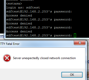
Lastly with an account that should be rejected:


Finally we have a working solution!

Hands-on with GNS3 1.0 (Alpha) - Part 1

Firstly this is not an April fool, lets get the clear now :)

I logged into my members account on GNS3 this morning to see that the alpha version was released a few hours ago.

There are two parts to the download, the GNS3 software (either for Linux or for Windows - I am using the Windows version here), and an OVA file for IOU.

The GSN3 install comes in the form of an all-in-one, and will install WinPcap (4.1.3), Wireshark (1.10.6), Dynamips, and GNS3.

Once GNS3 launches you need to put in your Early Release username and password, and acknowledge a disclaimer. Once that's done a DOS box pops up with some server details:

GNS3 server

The main screen looks very familiar, but just to make sure, lets look at the About dialog:

GNS3 ER 1.0 Alpha

Looks good so far!

The menu system looks the same as before.

The device menu does have another option though - for an IOU device:

IOU with GNS3

Which brings us back to the IOU OVA file we downloaded. Its a 150Mb file, and can be imported into VirtualBox by right clicking on it and selecting the option to open in VirtualBox.

Here I hit the first snag:

GNS3 errors

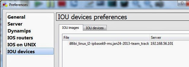
Once I had upgraded VirtualBox to 4.3.10 the import went fine, and the VM was started. I headed over to the webpage and uploaded my IOU image:

GNS3 IOU upload image
We then need to connect GNS3 to IOU, to do this we set a connection to our IOU VM:

Setting up IOU on GNS3


And specify where our license file is:

Setting up IOU on GNS3

You then need to add the image into GNS3 - which is just copying the path shown at the end of the IOU upload:

Add IOU device GNS3

Getting the correct license file was the hardest part. Because the IOU VM only has one VM adapter we cant install python to take advantage of the python IOU license generator. So instead I modified the script (just two lines, one for the hostid, and the other for the hostname), copied it to a linux VM that did have python installed and generated the file that way.

With my (working) license file I was able to then drag an IOU device onto my topology and start it up:

IOU working with GNS3

There is a very good reason that GNS3 does not come with ready-shipped iourc files - you can read why here.

But I am up and running now. I can drop another IOU device onto the topology and highlight both and see them in a group, the group allows configuration items such as interfaces to be added to multiple devices at once, which is a great feature:

GNS3 groups

I added a serial link whilst both routers were turned on (the IOS balked at adding an ethernet connection - but that might be a problem with the image), configured IP addresses and we have communication:

IOU working with GNS3

Thats it for the moment. I will continue playing around with it, but so far i am very impressed. More to follow soon.