In a previous post I wrote about how to integrate Cisco IPS modules with Microsoft 2008 NPS server, for Radius authentication.
Now we are going to cover how to integrate Cisco Nexus with radius. The format is very similar to the IPS setup, so it may be worth having a read of the first post to get an idea.
We start with some basic assumptions, and one caveat:
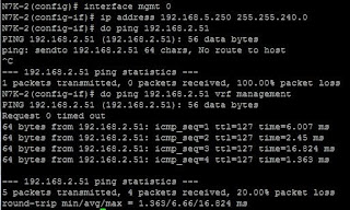
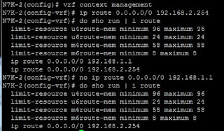
Your basic Nexus switch configuration is already in place and can ping your NPS server (via the management vrf)
You already have an NPS server in place serving clients.
I am using the Cisco Titanium Nexus 7000 emulator (but the same process should apply to the NX5000 series, I need to do this on real Nexus 5000's so if there are any differences I will update this post).
And now we have a client set up:
Now we create a policy to map access to the client. I have called this "TestNexus Admin", and the plan will be to have a read only policy added later on.
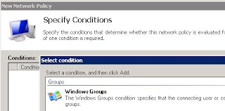
In the next window I start to specify the conditions, and will use the security group "sec-FW-admin", so click on Add to add a condition and select "Windows Groups"
Now you can add your specific groups.
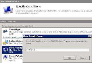
Next I add the Client Friendly Name, and use the same name I called the client:
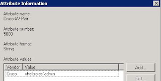
And now we can add a Vendor Specific entry:
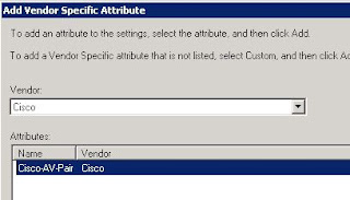
And for this entry we will use "shell-roles=*admin" (before anyone says this is wrong, please read the rest of the post to see why I havn't corrected this yet...)
Now we know that we can "talk" to the NPS box we can start setting up the radius parts.
We start by setting the radius key, it should match the key used to set up the client under NPS (again here we are using "nxnps123"). The 0 next to "key" means that its unencrypted.
Then we set the host (which we should have at least two of for redundancy), and create an aaa group and add the server to this. the last command tells the Nexus to use the management vrf to communicate with the server.
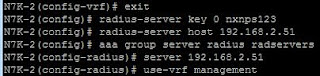
Now we can tell the Nexus to use radius for authentication, and we also tell it to keep track of errors:
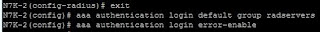
Finally, just in case our Radius server is down for any reason, the Nexus should use its local database for login:
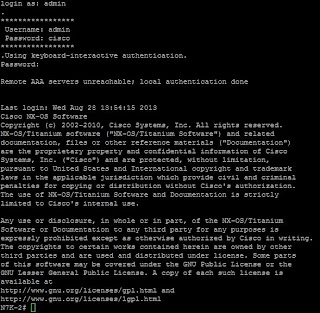
 Now we can test login!
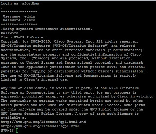 It works!
But we can't stop here. Like I pointed out earlier there was an issue with the shell:roles command within the NPS setup.
With the existing configuration we try saving the config:

So lets look at the privilege levels:

Well, -1 was never a good thing in my book. So I changed the AV-pair to "shell:roles=*"network-admin vdc-admin"", logged out, and back in again:
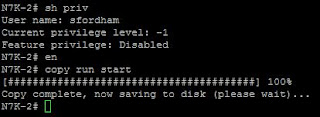
Now although the displayed privilege level is still showing -1, we can save the config.
Lastly I copied the profile in NPS, changed the Windows Group to one that has people we want with just read only access in it, and changed the role to network operator:
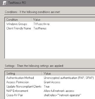
And again we test, this time we are expecting the copy run start to fail

Which it does, but they can still issue show commands, so the achieves exactly what is required.
Now we are going to cover how to integrate Cisco Nexus with radius. The format is very similar to the IPS setup, so it may be worth having a read of the first post to get an idea.
We start with some basic assumptions, and one caveat:
Your basic Nexus switch configuration is already in place and can ping your NPS server (via the management vrf)
You already have an NPS server in place serving clients.
I am using the Cisco Titanium Nexus 7000 emulator (but the same process should apply to the NX5000 series, I need to do this on real Nexus 5000's so if there are any differences I will update this post).
Nexus client and profile settings on Microsoft 2008 NPS
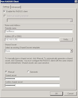
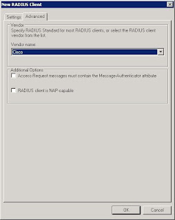
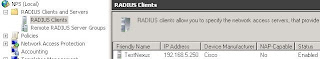
We start by adding a client onto the NPS, we give it a friendly name, specify the IP address and set the radius secret (here I am using nxnps123). I have also set the vendor name to Cisco.


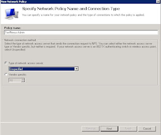
Now we create a policy to map access to the client. I have called this "TestNexus Admin", and the plan will be to have a read only policy added later on.

In the next window I start to specify the conditions, and will use the security group "sec-FW-admin", so click on Add to add a condition and select "Windows Groups"

Now you can add your specific groups.
Next I add the Client Friendly Name, and use the same name I called the client:

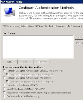
We keep the default of Access granted and move on till we see the "Configure Authentication Methods", here we select just PAP and SPAP:

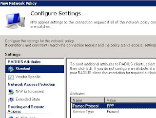
We can skip the "Configure Restraints" window and move on to "Configure Settings". Here we remove the two options under "Standard"


And for this entry we will use "shell-roles=*admin" (before anyone says this is wrong, please read the rest of the post to see why I havn't corrected this yet...)

And that's all the configuration on the Microsoft side (for the moment at least).
Nexus Radius setup and AAA Authentication
Just in case you havn't set up the basics on the Nexus the screenshots below show how to set the management vrf IP, and default routing, as well as confirming reachability to the NPS server:

Notice here that we have to specify vrf management in the ping command for it to work

Now we know that we can "talk" to the NPS box we can start setting up the radius parts.
We start by setting the radius key, it should match the key used to set up the client under NPS (again here we are using "nxnps123"). The 0 next to "key" means that its unencrypted.
Then we set the host (which we should have at least two of for redundancy), and create an aaa group and add the server to this. the last command tells the Nexus to use the management vrf to communicate with the server.

Now we can tell the Nexus to use radius for authentication, and we also tell it to keep track of errors:
Finally, just in case our Radius server is down for any reason, the Nexus should use its local database for login:

But we can't stop here. Like I pointed out earlier there was an issue with the shell:roles command within the NPS setup.
With the existing configuration we try saving the config:
So lets look at the privilege levels:
Well, -1 was never a good thing in my book. So I changed the AV-pair to "shell:roles=*"network-admin vdc-admin"", logged out, and back in again:

Now although the displayed privilege level is still showing -1, we can save the config.
Lastly I copied the profile in NPS, changed the Windows Group to one that has people we want with just read only access in it, and changed the role to network operator:

And again we test, this time we are expecting the copy run start to fail
Which it does, but they can still issue show commands, so the achieves exactly what is required.
Fallback on Nexus
Lastly we need to make sure that if the radius server is down, we can still get in. I stopped the NPS service and tried logging in. Login failed. I reconnected and tried logging in with the admin username and password, and got in:


.png "CCNA Salary scale")
.png "CCNP Salary scale")

.png "CCNA roles as a percentage of total")


.png)