Whilst trying to figure out how to block HSRP traffic over a QinQ link I had to set up a SPAN port, so thought it would be a good idea to cover it briefly here, as this is covered under exam topic 1.50.
At the destination end of the port would be a laptop (or workstation) running a program like Wireshark.
The commands a very simple.
We start by setting a monitor session, and each of these is numbered, and a source interface:
monitor session 1 source interface Fa1/0/2
We then set a destination interface for the same session number:
monitor session 1 destination interface Fa1/0/15
A SPAN source port can be a routed port, switch port, access port, trunk port, or an EtherChannel port.
Using this topology:
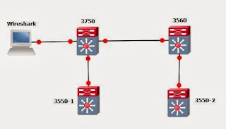
We have a laptop running Wireshark connected to Fa 1/0/15 on the 3750 switch.
the 3750 and 3550-1 are configured in an HSRP pair using the subnet 10.20.1.0/24 and the 3560 and 3550-2 are also in an HSRP pair using the subnet 10.10.1.0/24.
3560:
Wireshark shows us the following:
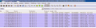
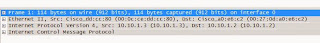
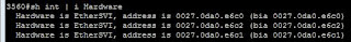
And we can see that everything is preserved nicely, including the MAC addresses.
That's the beauty of RSPAN, its invisible to the end user, it perfectly preserves the data, making it ideal for forensic analysis. network monitoring and network performance monitoring, and its quick.
In the configuration below we are monitoring incoming and outgoing traffic on vlan 10. For vlan 11 we are only monitoring incoming traffic, and only outgoing traffic for vlan 12. All traffic on Fa1/0/2 is being monitored and as this is a trunk port we have then filtered out vlans 1 through to 5 and also vlan 23. Lastly we are sending this to a remote VLAN as we did above.
What is a SPAN port?
A SPAN port or Switched Port ANalyzer offers a way of duplicating traffic from one port to another. This can be local to a switch (SPAN) or sent to a different switch (Remote SPAN or RSPAN). In a nutshell its a "free" network monitorAt the destination end of the port would be a laptop (or workstation) running a program like Wireshark.
Basic SPAN configuration
So imaging this scenario, interface FastEthernet1/0/2 is a trunk port to another switch, and we want to send a copy of all the traffic to a laptop connected to FastEthernet1/0/15 which is running Wireshark.The commands a very simple.
We start by setting a monitor session, and each of these is numbered, and a source interface:
monitor session 1 source interface Fa1/0/2
We then set a destination interface for the same session number:
monitor session 1 destination interface Fa1/0/15
A SPAN source port can be a routed port, switch port, access port, trunk port, or an EtherChannel port.
Basic RSPAN Configuration
A Remote SPAN is similar to SPAN, but it the destination is on a different switch. RSPAN does require a VLAN to be used to carry the traffic (and therefore must be allowed over any trunk links).Using this topology:

We have a laptop running Wireshark connected to Fa 1/0/15 on the 3750 switch.
the 3750 and 3550-1 are configured in an HSRP pair using the subnet 10.20.1.0/24 and the 3560 and 3550-2 are also in an HSRP pair using the subnet 10.10.1.0/24.
3560:
interface Vlan10
ip address 10.10.1.2 255.255.255.0
standby 10 ip 10.10.1.1
standby 10 priority 150
standby 10 preempt delay minimum 60
3550-2:
interface Vlan10
ip address 10.10.1.3 255.255.255.0
standby 10 ip 10.10.1.1
standby 10 priority 90
If we set out 3560 and 3750 up as follows:
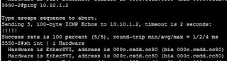
3560#conf t
3560(config)# vlan 100
3560(config-vlan)# remote-span
3560(config-vlan)# exit
3560(config)# monitor session 2 source vlan 10
3560(config)# monitor session 2 destination remote vlan 100

3750# conf t
3750(config)# vlan 100
3750(config-vlan)# remote-span
3750(config-vlan)# exit
3750(config)# monitor session 2 source remote vlan 100
3750(config)# monitor session 2 destination interface fastethernet 1/0/15
We can then ping from 3550-2 to the 10.10.1.2 interface on the 3560.

Wireshark shows us the following:

And we can see that everything is preserved nicely, including the MAC addresses.
That's the beauty of RSPAN, its invisible to the end user, it perfectly preserves the data, making it ideal for forensic analysis. network monitoring and network performance monitoring, and its quick.
Advanced SPAN and RSPAN concepts
We can be very selective with what we use our SPAN and RSPAN for. We can monitor traffic coming in (rx), or going out (tx) or both ways (which is the default). We can also filter out vlans that we don't want to have monitored.In the configuration below we are monitoring incoming and outgoing traffic on vlan 10. For vlan 11 we are only monitoring incoming traffic, and only outgoing traffic for vlan 12. All traffic on Fa1/0/2 is being monitored and as this is a trunk port we have then filtered out vlans 1 through to 5 and also vlan 23. Lastly we are sending this to a remote VLAN as we did above.
SW1#conf t
SW1(config)# vlan 100
SW1(config-vlan)# remote span
SW1(config-vlan)# exit
SW1(config)# monitor session 1 source vlan 10
SW1(config)# monitor session 1 source vlan 11 rx
SW1(config)# monitor session 1 source vlan 12 tx
SW1(config)# monitor session 1 source interface fa1/0/2>
SW1(config)# monitor session 1 filter vlan 1-5, 23
SW1(config)# monitor session 1 destination remote vlan 100


