In the third part of our series we are going to look at OSPF. This is forms part 2.40 of the CCIE Exam topics. So looking at this more specifically, what do we actually need to cover, and do we need to expand the topology?
2.40 lists the following as concepts that we need to know:
(a) Standard OSPF areas
(b) Stub area
(c) Totally stubby area
(d) Not-so-stubby-area (NSSA)
(e) Totally NSSA
(f) Link-state advertisement (LSA) types
(g) Adjacency on a point-to-point and on a multi-access network
(h) OSPF graceful restart
In our current topology we can implement a standard OSPF area, and one of either b through to e. We can do the point-to-point on G, but certainly not the multi-access part, and we can look at the LSA types.
So lets see how far we can go with some loopbacks and maybe throw some more routers into the topology as we go, but before we jump in lets have a quick look at OSPF in general and from there work out what we need to add to the existing topology.
I have covered some bits of OSPF before, looking at route redistribution, and also looking at BGP where OSPF is used at the IGP. These were fairly simple implementations of OSPF and just used a backbone.
OSPF router types
There are four different router types within OSPF, these will be highlighted in bold text below.The backbone is Area 0, which is required for OSPF to function. As a general rule all other areas must connect to to Area 0. Routers can belong to more than one area and these routers that have say an interface in Area 0 and an interface in Area 1 are known as Area Border Routers (ABR). Because it has an interface in the backbone (area 0) it is called a Backbone router as well. If a router has a connection to area 0 but also connects to another Autonomous System (like the Internet), or redistributes another routing protocol onto OSPF it is called an Autonomous System Border Router (ASBR), in our case because R2 connects (at the moment any way) to the RIP network, it would be considered an ASBR. If a router only exists within one area then it is called an Internal Router.
So that's router types covered and we have touched on areas, so lets look at area types.
OSPF Area types
We know of one area, and that's area 0, we can have any number of areas and without any special commands these will be known as "Standard Areas", but we also know that we need to know of other area types. Area types determine what LSAs will be allowed in. LSAs are Link State Advertisements and we'll have a nice little table of these in a short while, but the area types are:Standard (we have just covered this)
Stubby - A stubby area prevents external routes from flooding into an area. No ASBRs are allowed in a stub area. The stubs ABR will inject a default route to allow the router to reach an external network.
Totally Stubby Area - prevents inter-area and external routes from flooding into an area, again the ABR will inject a default route.
Not So Stubby Area - prevents external routes from flooding into an area unless those external routes originated from an ASBR within the NSSA area.
Totally Not So Stubby Area - Prevents both inter-area and external routes flooding into an area unless originated from an ASBR.
OSPF LSAs
| Name | Type Code | Generated by | Contains | Sent to |
| Router LSA | 1 | All routers in OSPF | A list of all links local to the router | All other routers in local area |
| Network LSA | 2 | All Designated Routers (DR) in OSPF | List of all routers attached to the DR | |
| Network Summary | 3 | All ABRs | List of all destination networks | other areas to allow inter-area communications |
| ASBR Summary LSA | 4 | All ABRs | A route to ASBRs in OSPF | local area, so Internal routers know how to exit the AS |
| External LSA | 5 | ASBRs | Routes to destination networks outside of OSPF | All areas in OSPF |
| Multicast OSPF | 6 | |||
| NSSA External LSA | 7 | ASBRs in NSSA areas |
I have left LSA types 6 and 7 purposefully uncompleted as type 6 is not needed at the moment and type 7 will be covered in more detail later on.
So what can we configure at the moment given our existing topology? Well, we have R2 and R3 all ready earmarked for our OSPF portion and we could either have R2 as part of our RIP network, or instead make R4 part of our OSPF network, so lets do that instead. So R2 and R4 can act as a "standard" area. R3 we can make one of the other area types, as well as R1. So let's make R1 a stubby area. Later on in our series we'll see if we can add some NATing to R1 and have something purposeful we can use for our end to end tests.
R3 is not going to act as out jumping point to three more areas - a Totally Stubby, a Not So Stubby and a Totally Not So Stubby Areas, another alternative would be to use some frame relay between R3 and some other routers.
I am going to go away and have a play around and see what I can come up with... be back soon...
OK so I am back now, many hours later. It looks like the frame relay isn't going to work, and you can read why here. So instead the topology will be expanded again to include more routers. I have now added R11, R12, R13 and R14. R1 will be a stubby area, R2 will be an ABR, and R4 will be an ASBR. R3 will be an internal router, R11 will be an ABR connecting to a Totally Stubby Area (R12), a Not So Stubby Area (R13) and a Totally Not So Stubby Area (R14), and our topology will look like this:

Creating the OSPF Backbone
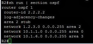
The backbone relies on area 0 and our area 0 will extend from R2 to R3 so we assign the 10.1.1.0 network to this area. As R1 will be a stub area (area 2) we assign the 1.2.3.0 subnet to this area and specify "area 2 stub". Area 3 (10.1.6.0) connects to R4. The important thing across all our configurations is to set the router-id to something we should be able to easily identify.
Configuring R1 as a stub
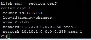

The command "area 2 stub" is all thats needed (on both routers) to set up a stub area. We can see that OSPF is playing nicely with our PPP Multilink from part 2.
R3

R11

R12

We can see that R11 has sent over some OSPF inter area routes for the 10.1.1.0 and 10.1.2.0 nertworks.

Configure R12 as Totally Stubby Area
We head back to R11 and set as follows:
we add the "area 5 stub no-summary" command, we do similar on R12:


We can now see that R11 instead of sending routes for 10.1.1.0 and 10.1.2.0 sends a default route. Can we still reach R2?

Configuring R13 as a Not So Stubby Area
We configure R11 by adding the command "area 6 nssa", and do so again on R13
R13's routing table

So this is exactly how we would expect to see it.
Configuring R14 as a Totally Not So Stubby Area
On R11 we add the line "area 7 nssa no-summary" under the OSPF routing process and set up R14 as below:

Now at this time we can see that the Loopback address on R1 (10.10.1.1) is not seen by, or accessible to the other routers. So how can we get it visible?
Stubs, loopbacks and virtual-links
We can't make the other routers aware of the 10.10.1.0 network until we take the 1.2.3.0 network out of area 2 and put it in area 0, and also set it not to be a stub.

Virtual-links would not have worked in this instances as a stub zone cannot contain a virtual link:
We can have area 1 as a stub, and could add routers to one of the other interfaces on R1 and have a full stub zone, but hopefully at this stage you get the general idea or the area types.
We will revisit how the different area types come in to play when we move on to RIP and start redistributing some routes from RIP into OSPF in part 4 of The BIG lab. We havn't covered part G yet, but let;'s just go through OSPF graceful restart before we finish.