As part of the big lab I am doing I want to do some work with Frame Relay. Nothing to exciting at the moment, but I do want to touch on it.
So with IOU I want a Frame Relay connecting to four other routers in a hub and spoke topology. Pretty simple right?
Well using this netmap:
5:0/0 1:0/0
5:0/1 2:0/0
5:0/2 3:0/0
5:0/3 4:0/0
I get what I want:

And I can set up my FR switch as follows:
hostname FR1
!
boot-start-marker
boot-end-marker
no aaa new-model
clock timezone CET 1 0
mmi polling-interval 60
no mmi auto-configure
no mmi pvc
mmi snmp-timeout 180
ip auth-proxy max-login-attempts 5
ip admission max-login-attempts 5
ip cef
no ipv6 traffic interface-statistics
no ipv6 cef
frame-relay switching
multilink bundle-name authenticated
crypto pki token default removal timeout 0
redundancy
!
interface Serial0/0
description Connected to R1
no ip address
encapsulation frame-relay
no keepalive
serial restart-delay 0
no frame-relay inverse-arp
frame-relay lmi-type ansi
frame-relay intf-type dce
frame-relay route 102 interface Serial0/1 201
frame-relay route 103 interface Serial0/1 301
frame-relay route 104 interface Serial0/1 401
!
interface Serial0/1
description Connected to R2
no ip address
encapsulation frame-relay
shutdown
no keepalive
serial restart-delay 0
frame-relay intf-type dce
frame-relay route 201 interface Serial0/0 102
!
interface Serial0/2
description Connected to R3
no ip address
encapsulation frame-relay
no keepalive
serial restart-delay 0
frame-relay intf-type dce
frame-relay route 301 interface Serial0/0 103
!
interface Serial0/3
description Connected to R4
no ip address
encapsulation frame-relay
no keepalive
serial restart-delay 0
no frame-relay inverse-arp
frame-relay lmi-type ansi
frame-relay intf-type dce
frame-relay route 401 interface Serial0/0 104
!
Ok so nothing too complicated here.
Looking at R1 and R4 (truncated):
hostname R1
!
interface Serial0/0
no ip address
encapsulation frame-relay
serial restart-delay 0
frame-relay lmi-type ansi
!
interface Serial0/0.14 point-to-point
ip address 10.1.14.1 255.255.255.0
frame-relay interface-dlci 104
!
hostname R4
!
interface Serial0/0
no ip address
encapsulation frame-relay
serial restart-delay 0
frame-relay lmi-type ansi
!
interface Serial0/0.41 point-to-point
ip address 10.1.14.4 255.255.255.0
frame-relay interface-dlci 401
!
I should be able to ping R4 from R1 and R1 from R4, but sh ip int bri shows that the sub-interfaces are down/down and the physical interface is up/down. If I add "no keepalive" to the physical interfaces they come up, but I still can't ping across them:

So the config looks ok, the interfaces are up, and we know from part two of the big lab series that serial interfaces do work on IOU, so whats the problem? Well it looks to be an issue in IOU:

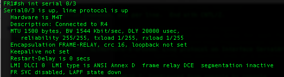
Look at the result of the "sh int serial 0/3" it clearly shows that its set to Frame Relay DCE, but the result of the "sh controllers serial 0/3" shows a very different story:

It's showing a cable type of DTE.
Having a look at the netmap tutorial on Route Reflector page it shows a Frame Relay switch sitting in the middle of a bunch of routers and the netmap has 107 at the end of the connections, 107 being the Link-Layer header type for Frame Relay. So if I change my netmap to:
5:0/0 1:0/0 107
5:0/1 2:0/0 107
5:0/2 3:0/0 107
5:0/3 4:0/0 107
I get this:

Clearly this is not what I am looking for!
Means I have to rethink how my big lab topology will pan-out. I am guessing it'll be without Frame-Relay for the time being! Even Andrea over at Route Reflector states that serial interfaces appear as DTE in the FAQs.
If anyone knows how to get around this, I'd love to hear from you. I have tried a number of different images but so far nothing works.
I am going to continue playing around, so hopefully will be able to pull something out of the hat, unless there is someone out there that can point me in the right direction...
*Update* GNS3 works fine with the same configs.
5:0/1 2:0/0 107
5:0/2 3:0/0 107
5:0/3 4:0/0 107
I get this:
Clearly this is not what I am looking for!
Means I have to rethink how my big lab topology will pan-out. I am guessing it'll be without Frame-Relay for the time being! Even Andrea over at Route Reflector states that serial interfaces appear as DTE in the FAQs.
If anyone knows how to get around this, I'd love to hear from you. I have tried a number of different images but so far nothing works.
I am going to continue playing around, so hopefully will be able to pull something out of the hat, unless there is someone out there that can point me in the right direction...
*Update* GNS3 works fine with the same configs.
6 comments
commentsJust add an Ethernet card on the "frame relay" switch.
ReplyThen, the serial interfaces will be renamed as s1/0 s1/1...
And the DCE cable will works !
Mike.
Great tip, Mike! thanks for your help!
ReplyI used L3 12.4 TPG image and got it working.
ReplyYou might want to activate
debug frame-relay switching… in the FR node
debug frame-relay packets… in the PE & CE nodes
----------------------------------------FR
frame-relay switching
interface Serial0/0
description -> PE
encapsulation frame-relay ietf
frame-relay lmi-type ansi
frame-relay intf-type nni
frame-relay route 102 interface Serial0/1 201
no shutdown
interface Serial0/1
description -> CE
encapsulation frame-relay ietf
frame-relay lmi-type ansi
frame-relay intf-type dce
frame-relay route 201 interface Serial0/0 102
no shutdown
----------------------------------------PE
interface Serial2/0
description -> FR
encapsulation frame-relay ietf
frame-relay lmi-type ansi
frame-relay intf-type nni
no shutdown
interface Serial2/0.100 point-to-point
description -> CE
ip vrf forwarding test
ip address 1.0.0.1 255.255.255.252
frame-relay interface-dlci 102 ietf
----------------------------------------CE
interface Serial2/0
description WAN
encapsulation frame-relay ietf
frame-relay lmi-type ansi
frame-relay intf-type dte
no shutdown
interface Serial2/0.100 point-to-point
description WAN
ip address 1.0.0.2 255.255.255.252
frame-relay interface-dlci 201 ietf
oh, great, i just commented thrice...yep, approval
Replythird times a charm!
ReplyNice one!
Reply